Task 7 - Configuring Service Device Insertion
Overview
In this lab, attendees will configure inter-tenant traffic flows across active/standby firewalls within a VXLAN EVPN data center environment. The focus is on integrating firewalls into a VXLAN EVPN Single-Site architecture, with Multi-Site support to be introduced in the next release of Nexus Dashboard.
Task 5 Automation is Mandatory
In order to continue with this task you must have completed the automation one
Deployment Models for Service Devices
While there are multiple deployment models for service devices, such as:
- Firewall as Default Gateway
- Perimeter Firewall
- Enhanced Policy-Based Redirection
this lab specifically covers a single deployment model, the Firewall as Default Gateway.
Through this hands-on exercise, attendees will configure and validate the active/standby firewall setup.
Other available options, not covered in this lab, include:
- Active/Active Firewall
- Independent Nodes and/or Clusters
Scenario
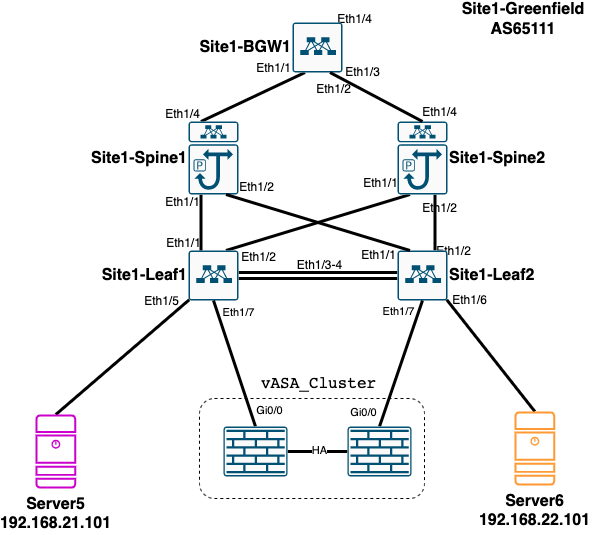
In this task, you will integrate an existing Active/Standby firewall cluster into the Site1-Greenfield VXLAN EVPN Fabric. The firewall is configured to protect two internal network segments:
l2_network_21l2_network_22
These network segments were created using Ansible automation in a previous task and have their gateways configured on the firewall. Consequently, NDFC and Nexus switches recognize them as Layer 2-only networks.
Note
This setup does not use the Distributed Anycast Gateway, which offers better performance. However, this configuration reflects a common real-world deployment scenario.
Objective
The goal is to enable reachability between these networks and the broader environment. This involves:
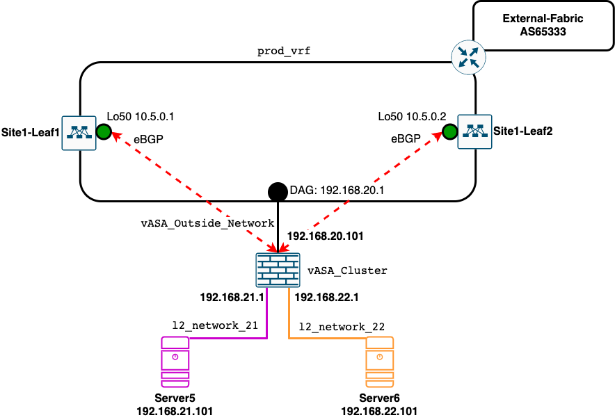
- Establishing an eBGP session between the fabric and the firewalls
- Exchanging routing information about the networks protected by the firewall and those available in the
production_vrf
Note
Only the active firewall will establish an eBGP session with both leaf switches.
Diagram
Physical Diagram
Logical Diagram
Configuration - Prepare the Environment
Step 1: Access the Fabric
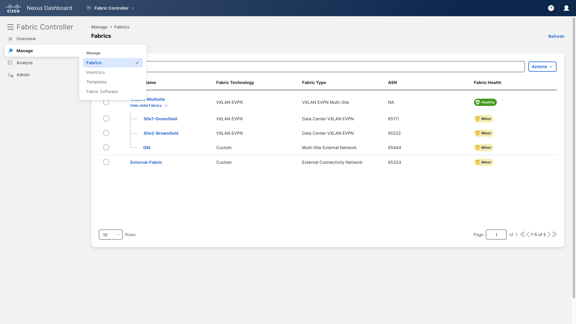
- Go to the Site1-Greenfield main page
- Navigate to Manage > Fabrics
- Double-click on Site1-Greenfield
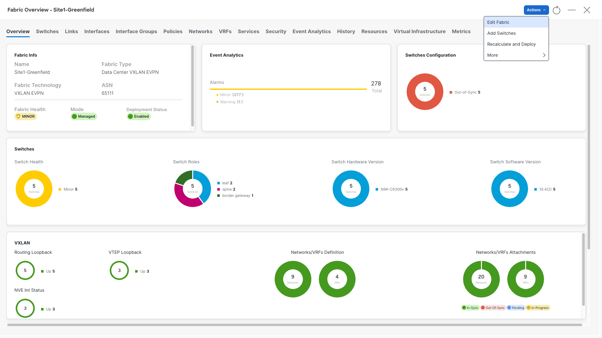
Step 2: Edit the Fabric Settings
- Click on Actions
- Select Edit Fabric
Step 3: Enable the loopback auto-assignment
- Click on the Resources and scroll down until you:
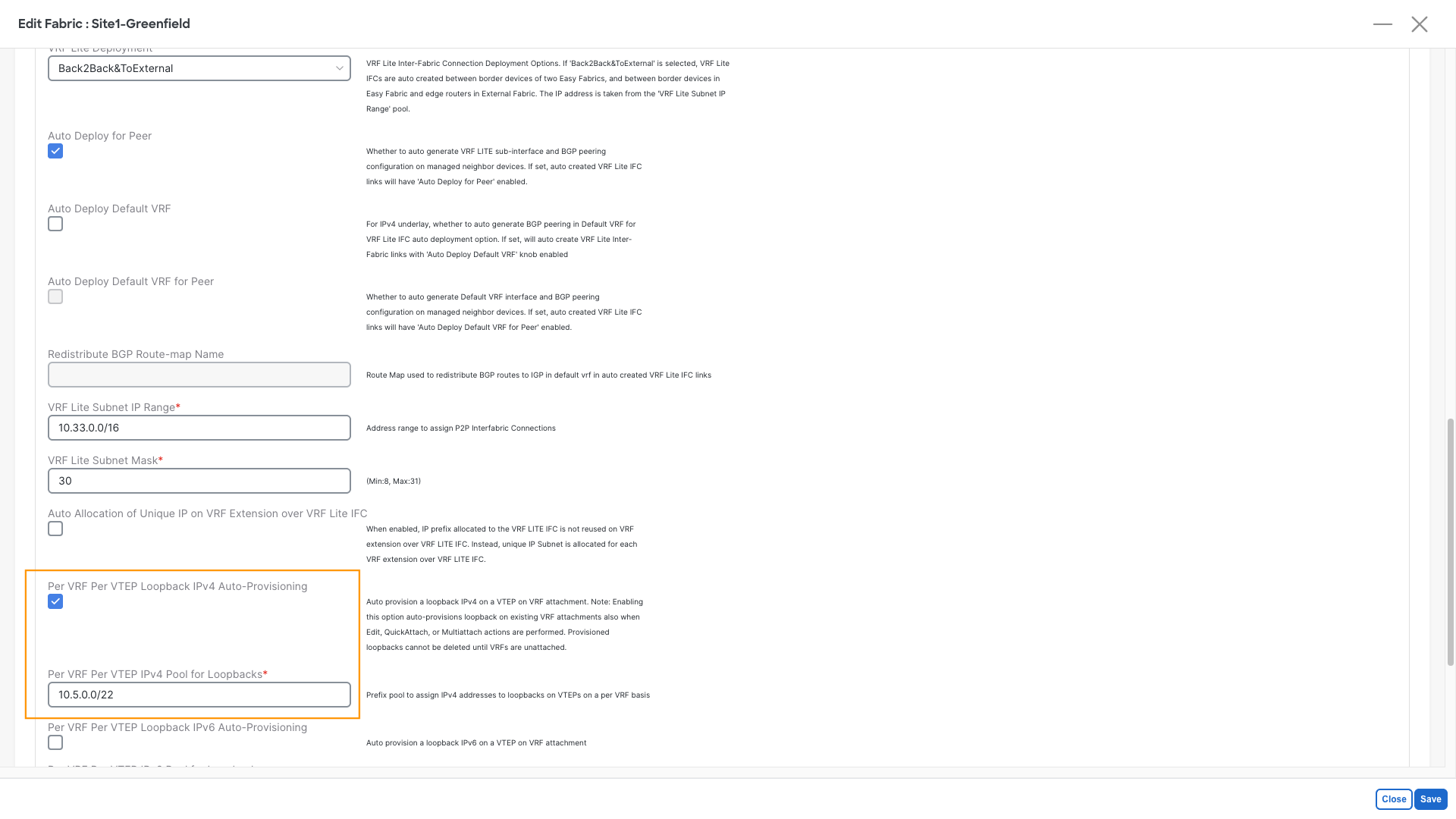
- Enable Per VRF Per VTEP Loopback IPv4 Auto-Provisioning
- In the below Per VRF Per VTEP IPv4 Pool for Loopbacks insert 10.5.0.0/22
- Click Save
In addition to the recent changes, we will manually define the Loopback IPs for two key reasons:
- Loopback IPs are only added to new VRF attachments, leaving existing ones unchanged
- We need to ensure that our leaf switches are configured with the same IPs that the virtual firewalls uses as BGP neighbors
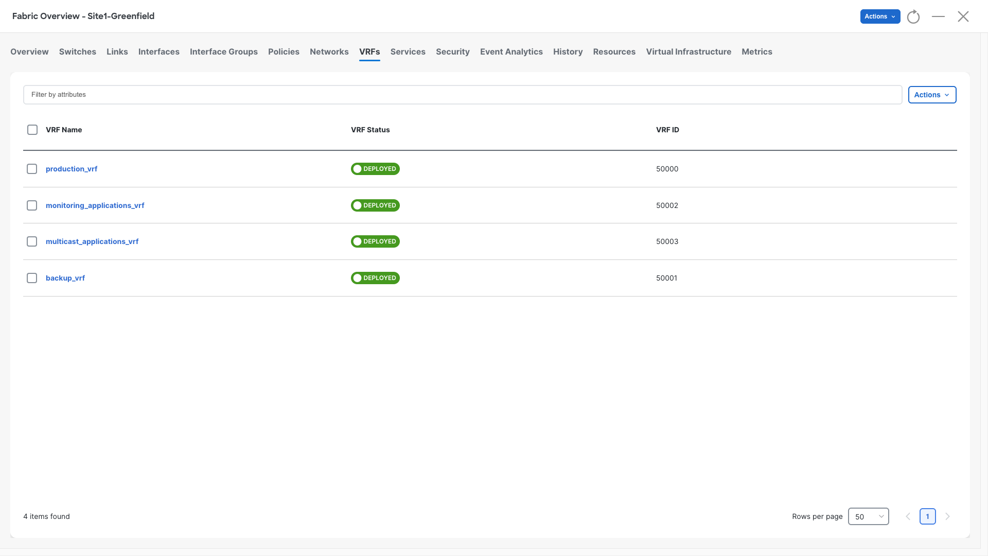
Step 4: Navigate to VRFs
- Open the VRFs section
- Double-click on production_vrf
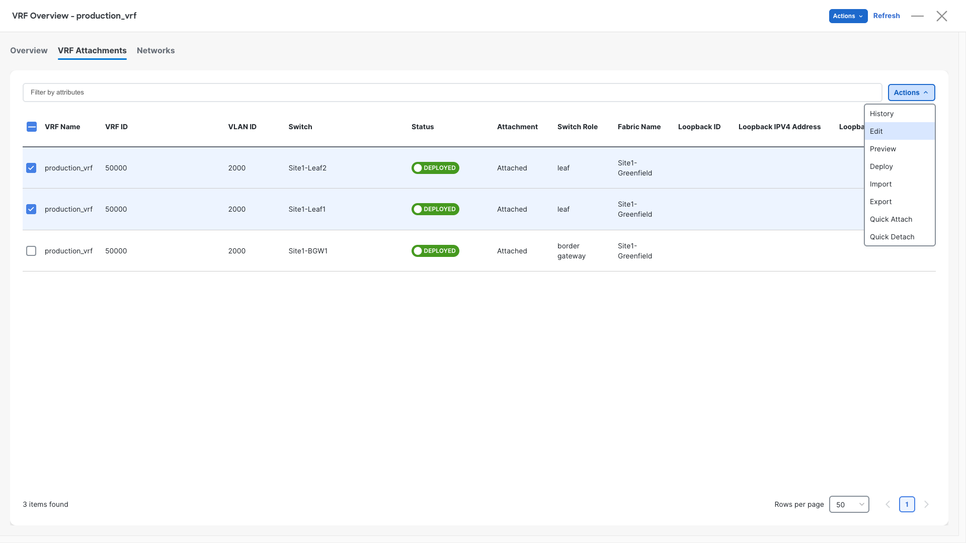
Step 3: Attach VRFs to Leaf Switches
- Open the VRF Attachments section
- Select the rows for Site1-Leaf1 and Site1-Leaf2
- Click Actions > Edit
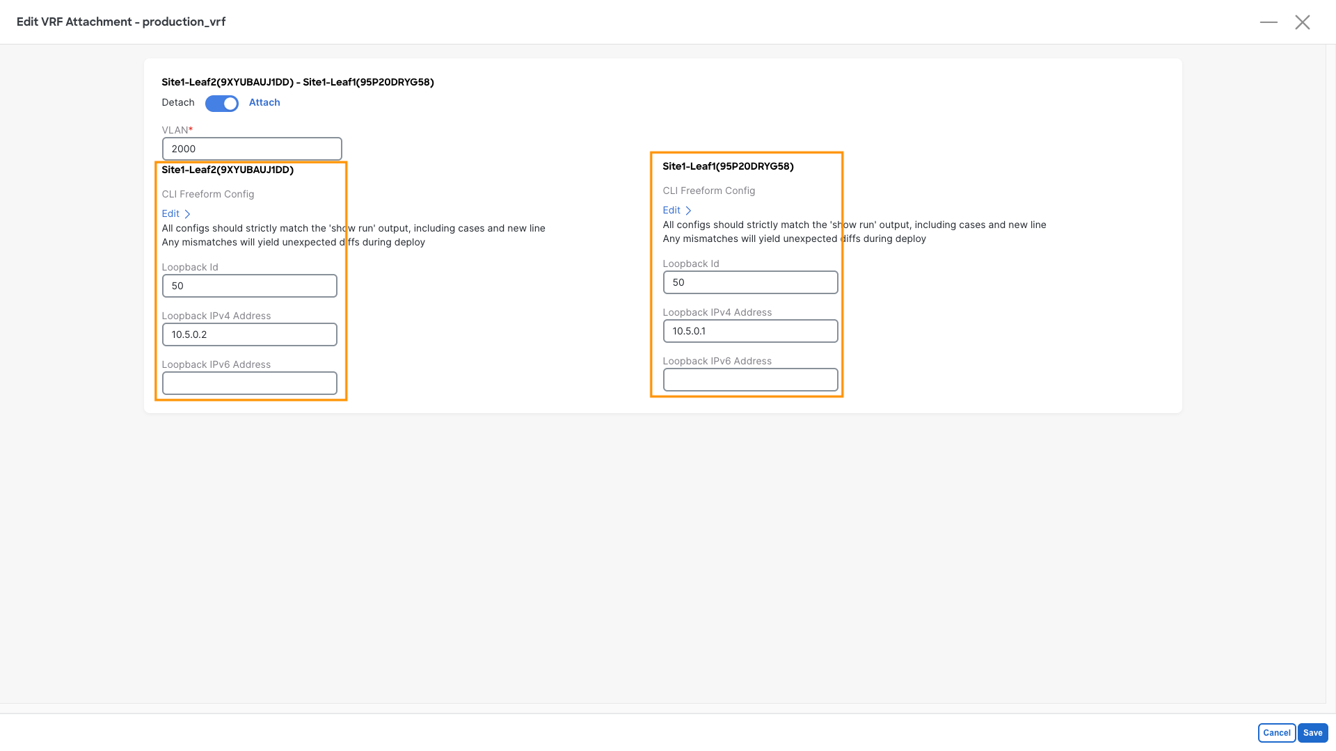
Step 4: Configure IPv4 Loopbacks
- Add IPv4 loopbacks for both leaf switches using the details below:
| Leaf | Loopback ID | IP Address |
|---|---|---|
| Site1-Leaf1 | 50 | 10.5.0.1 |
| Site1-Leaf2 | 50 | 10.5.0.2 |
Step 5: Recalculate and Deploy
- Perform a Recalculate and Deploy on the fabric
Verification - Let's verify the reachability of the loopback
This task is optional
If you are running short on time, consider skipping this part and jumping straight to the next Configurations section. This section is here to show that configurations are incomplete and explain you the reason.
Step 1: Access Site1-Leaf1
- Open the MTPutty terminal:
- Double-click on Site1-Leaf1
- Run the following commands and check the result:
Site1-Leaf1
show ip route 10.5.0.1 vrf production_vrf
show ip route 10.5.0.2 vrf production_vrf
Step 2: Evaluate the Output
- Look at the output provided with the above commands:
- 10.5.0.1 is known as a local interface, as expected
- 10.5.0.2, configured on Site1-Leaf2, is missing, and the RIB recursively points to the default route
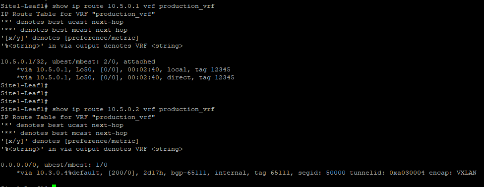
Why is this happening?
By default, external prefixes (route-type 5) are discarded when received from the vPC peer because their nexthop will be VTEP's secondary shared IP address.
There are a few ways to resolve this problem. Today, we will enable the vPC advertise-pip option.
Configuration - Fixing the Loopback Reachability
Step 1: Access the Fabric
- Go to the Site1-Greenfield main page:
- Navigate to Manage > Fabrics
- Double-click on Site1-Greenfield
Step 2: Edit the Fabric Settings
- Click on Actions
- Select Edit Fabric
Step 3: Enable the vPC advertise-pip
- Click on vPC
- Enable vPC advertise-pip
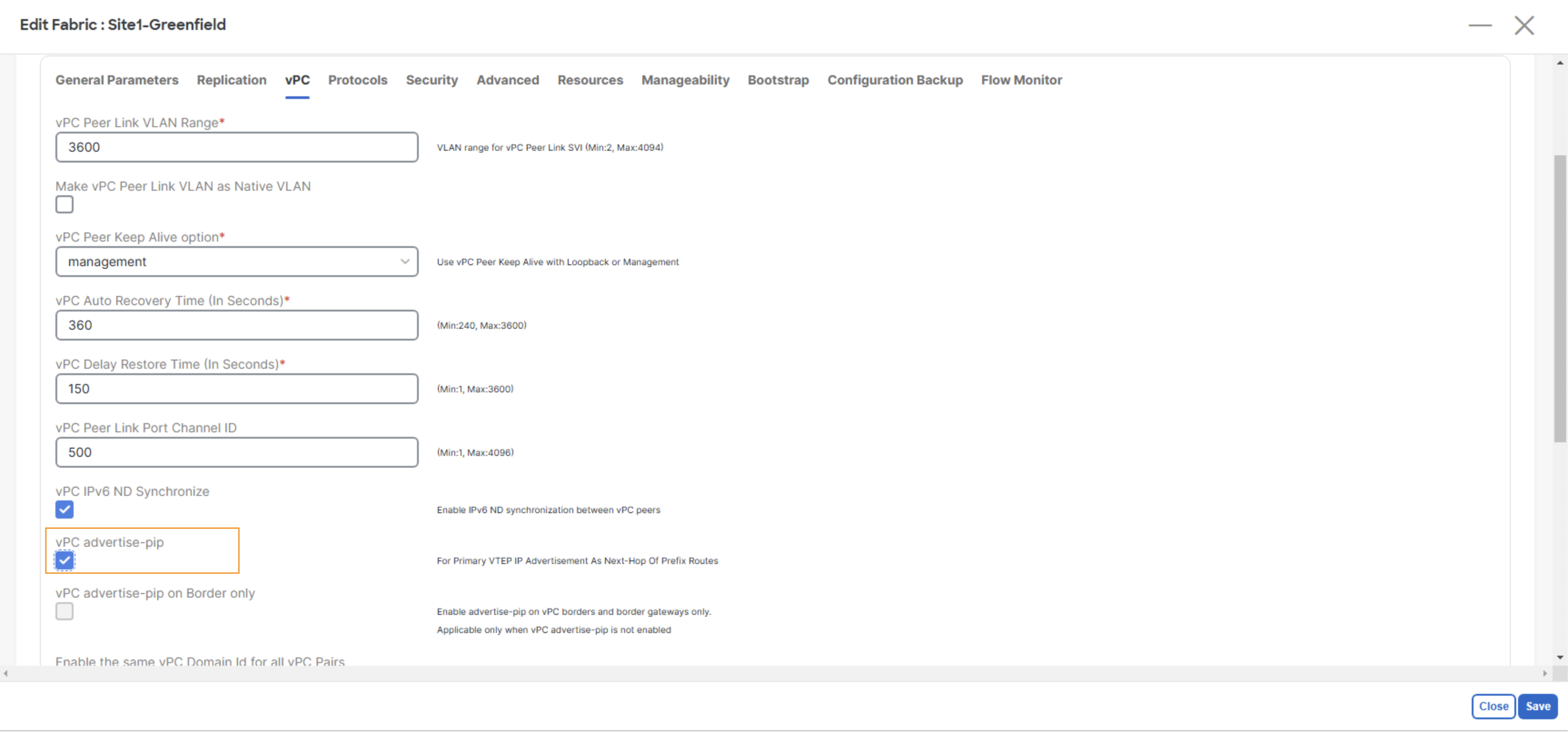
Step 4: Save the Configuration
- Click the Save button
Step 5: Recalculate and Deploy
- Perform a Recalculate and Deploy on the fabric
Verification - Verifying the Loopback Again
Step 1: Access Site1-Leaf1
- Open the MTPutty terminal:
- Double-click on Site1-Leaf1
- Run the following commands and check the result:
Site1-Leaf1
show ip route 10.5.0.1 vrf production_vrf
show ip route 10.5.0.2 vrf production_vrf
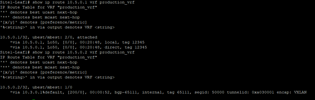
Step 2: Evaluate the Output
- Look at the output provided with the above commands:
- 10.5.0.1 is known as a local interface
- 10.5.0.2 is now learned and pointing to the other vPC peer VTEP address
Configuration - Configure the Firewall Cluster in NDFC
Service Cluster
Step 1: Access the Fabric
- Go to the Site1-Greenfield main page:
- Navigate to Manage > Fabrics.
- Double-click on Site1-Greenfield.
Step 2: Define the Service Custer
- Go to the Services section:
- Click on Service Clusters
- Click on Add Service Cluster
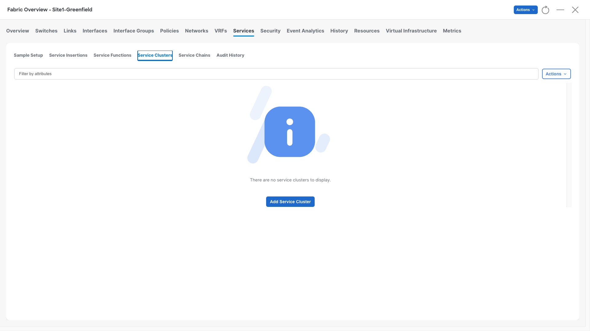
The Service Cluster contains information about the physical topology on how a firewall cluster is connected to the fabric and what is its redundancy model. This together with the Service Function and the Service Insertion will help NDFC rendering the configuration.
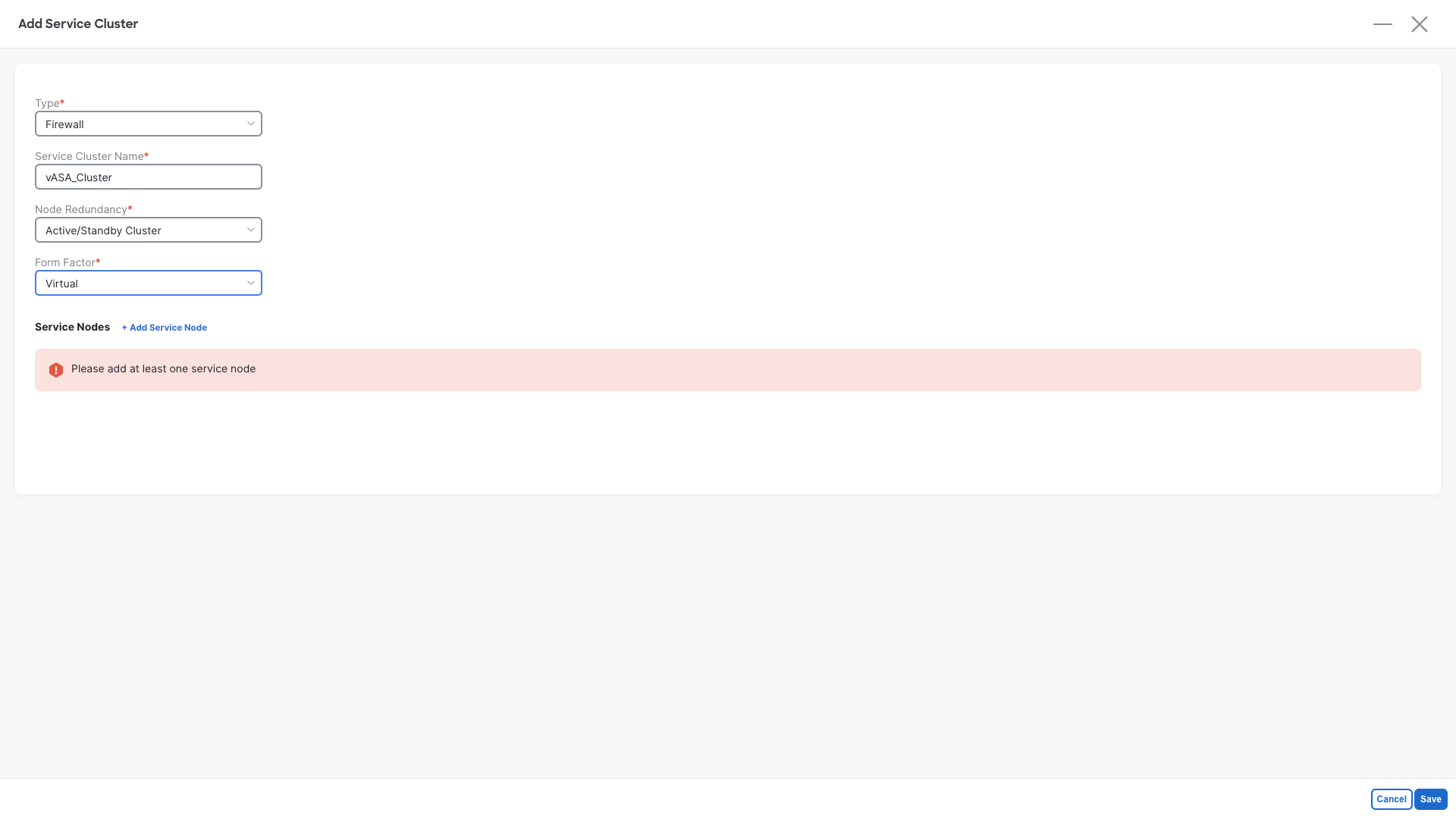
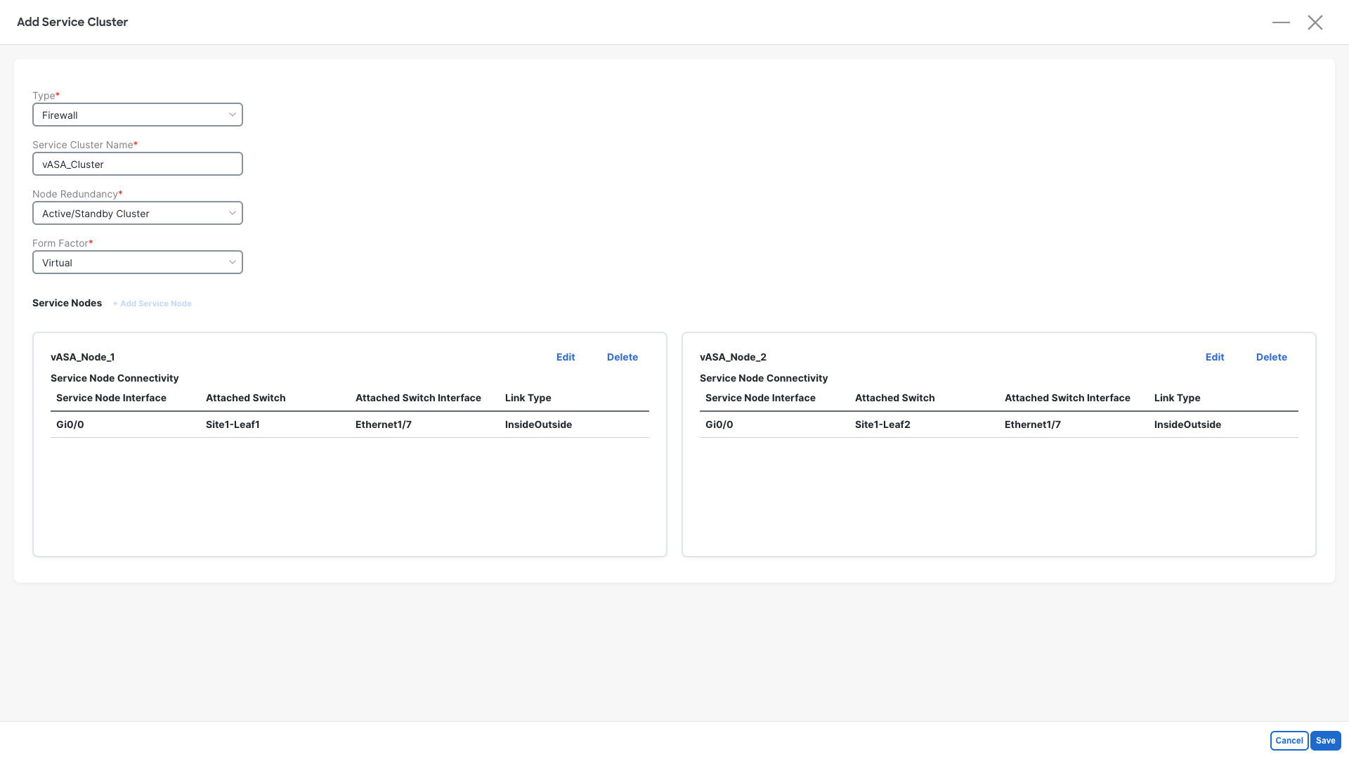
Step 3: Define the Cluster properties:
- Type: Firewall
- Service Cluster Name: vASA_Cluster
- Node Redundancy: Active/Standby Cluster
- Form Factor: Virtual
- Click on +Add Service Node
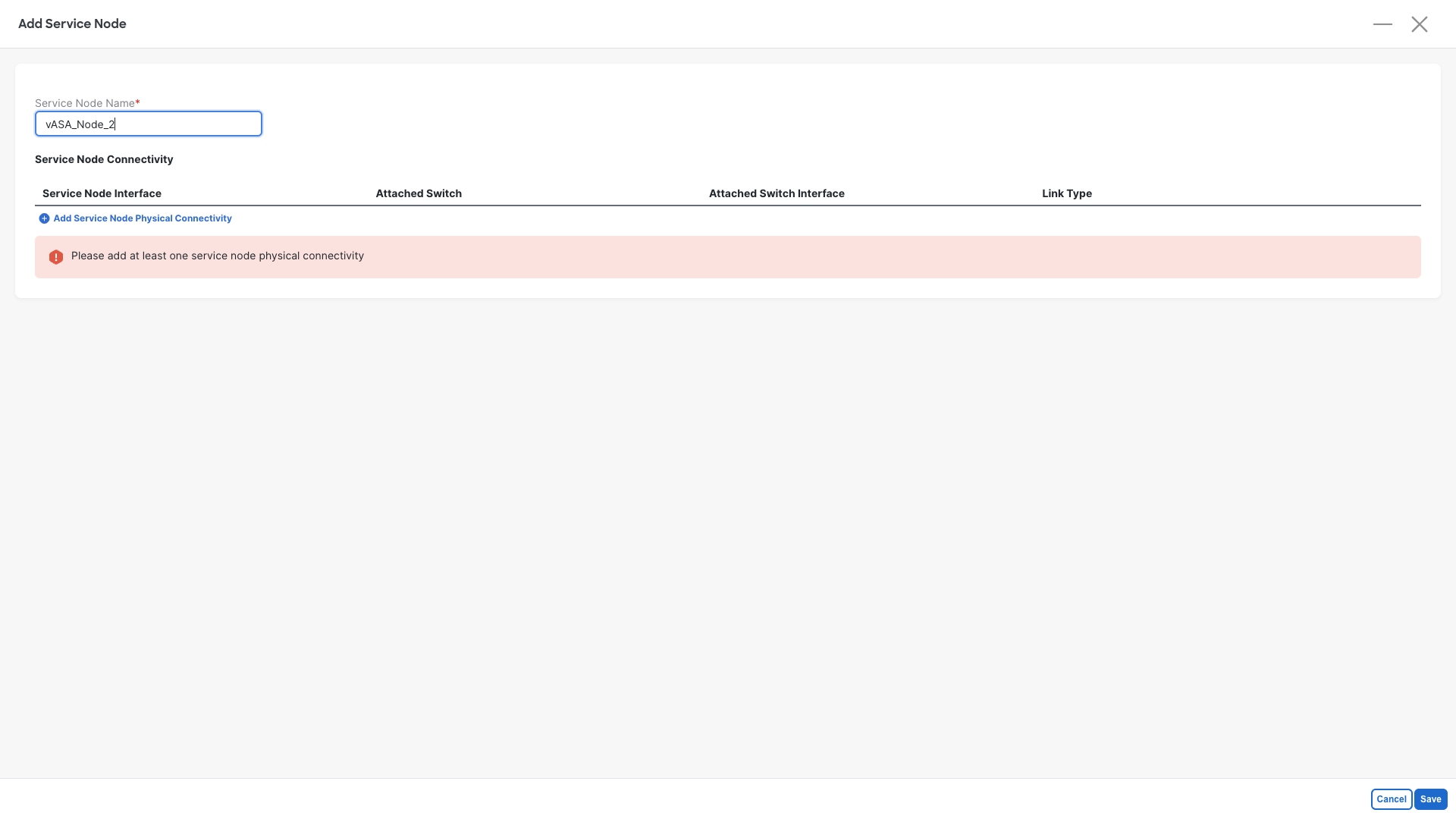
Step 4: Define the First Cluster Member:
- Service Node Name: vASA_Node_1
- Click on Add Service Node Physical Connectivity

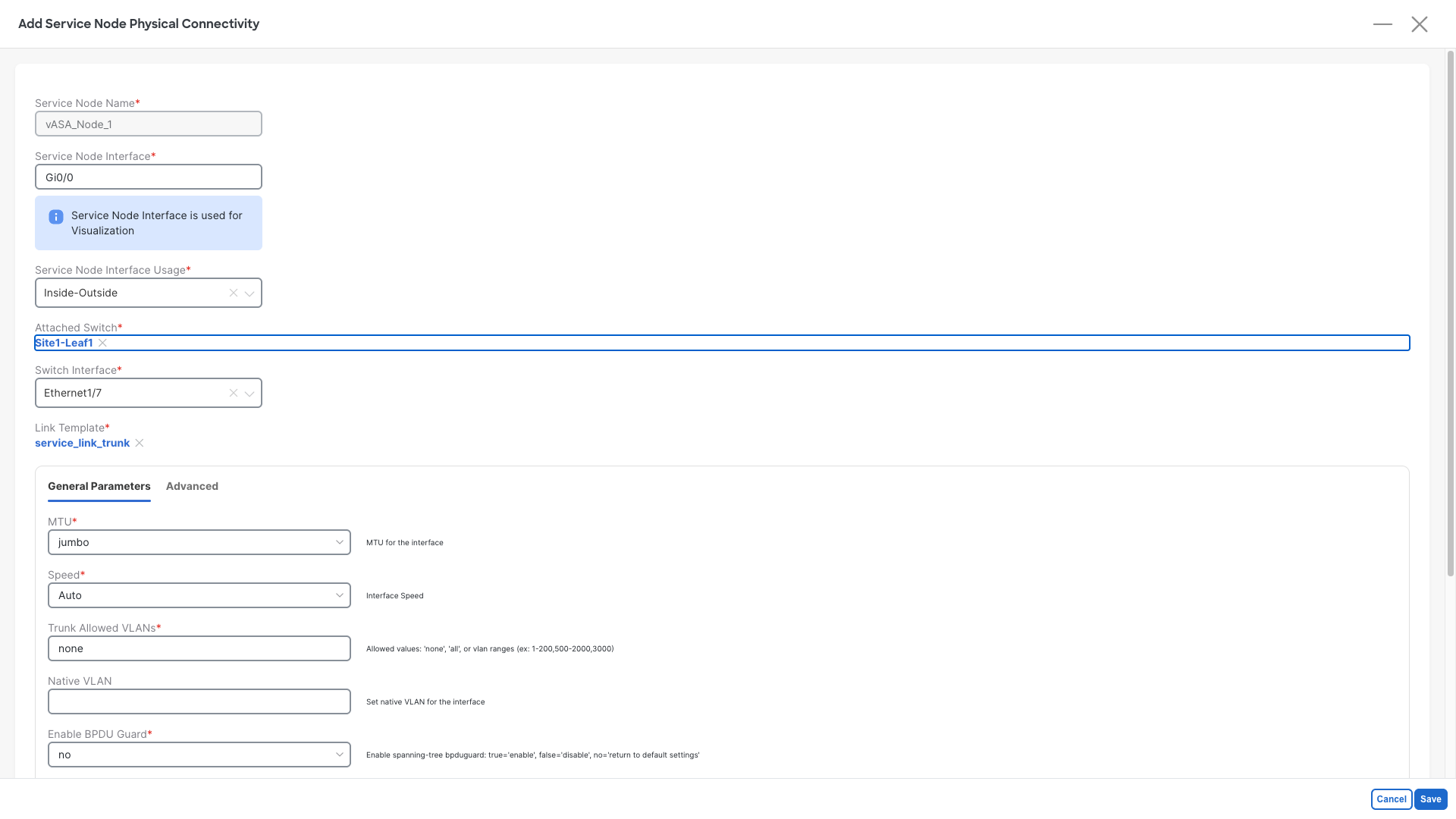
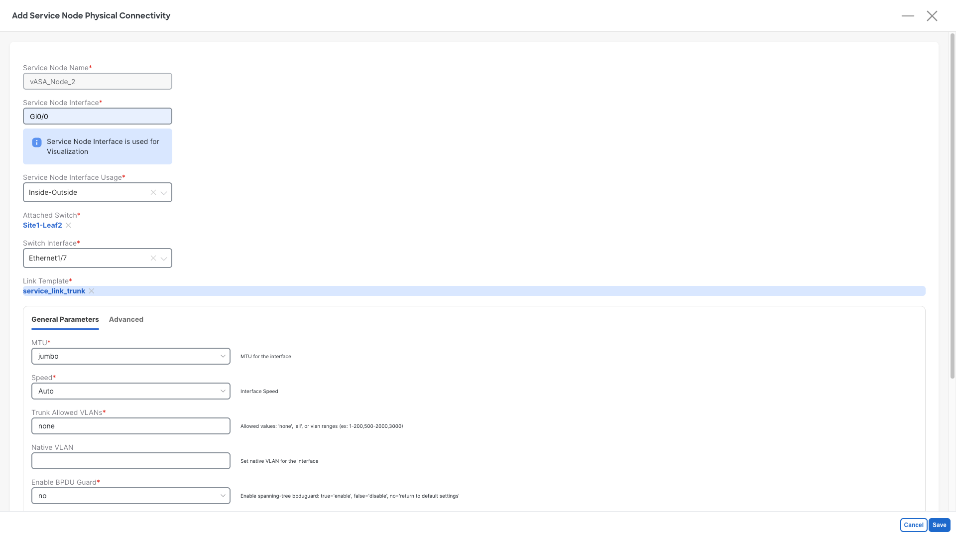
Step 5: Set the interfaces for the First Cluster Member
- Service Node Interface: Gi0/0
- Service Node Interface Usage: Inside-Outside
- Click on Attached Switch - Select - and pick the Site1-Leaf1 node
- Switch Interface: Ethernet1/7
- Do not change the template and/or the parameters
- Click on Save
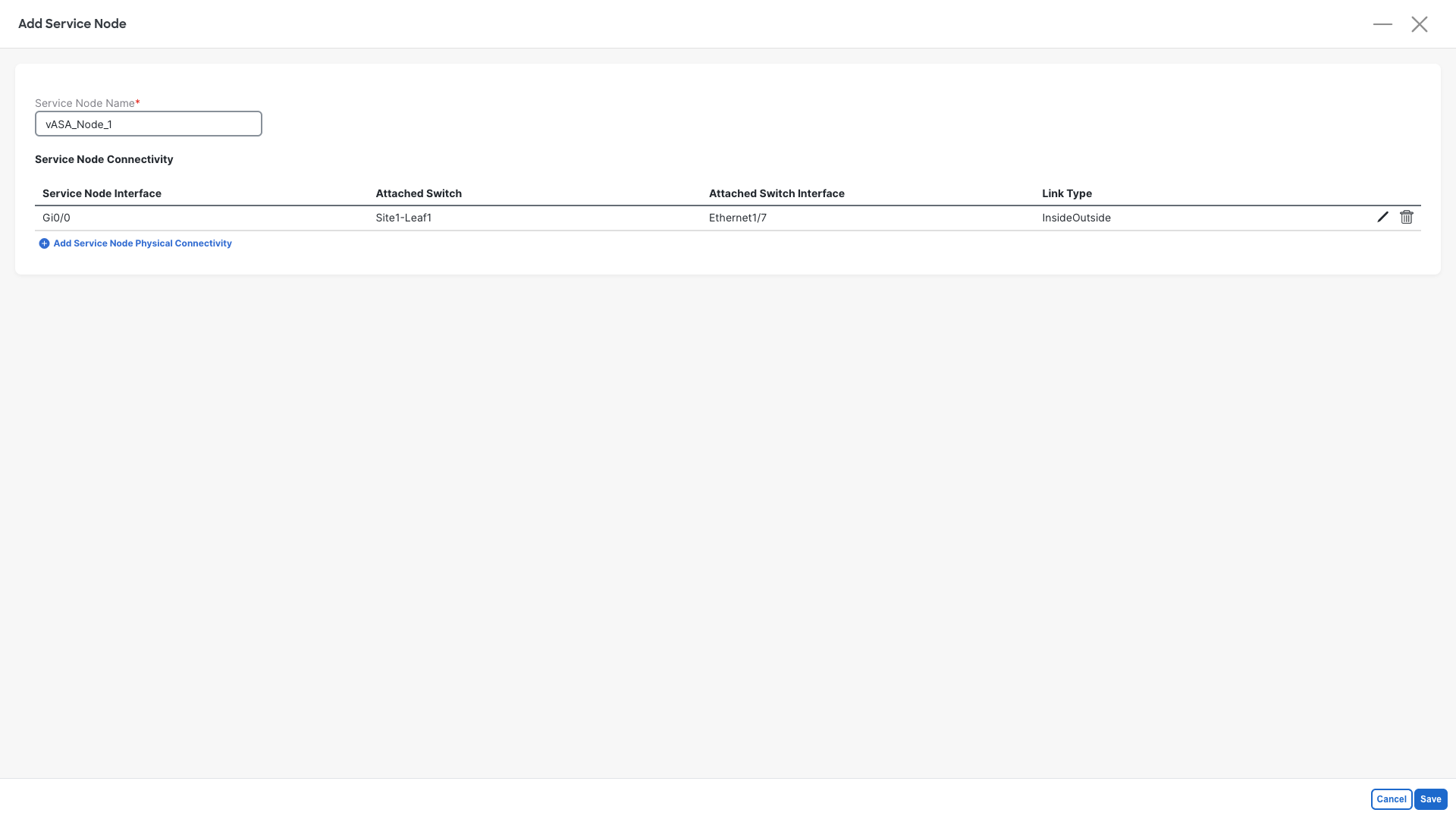
Step 6: Save the First Cluster Member
- Click on Save
Step 7: Add the Second Cluster Member
- Click on Click on +Add Service Node
Step 4: Define the Second Cluster Member:
- Service Node Name: vASA_Node_2
- Click on Add Service Node Physical Connectivity
Step 5: Set the interfaces for the Second Cluster Member:
- Service Node Interface: Gi0/0
- Service Node Interface Usage: Inside-Outside
- Click on Attached Switch - Select - and pick the Site1-Leaf2 node
- Switch Interface: Ethernet1/7
- Do not change the template and/or the parameters
- Click on Save
Step 6: Save the Second Cluster Member
- Click on Save
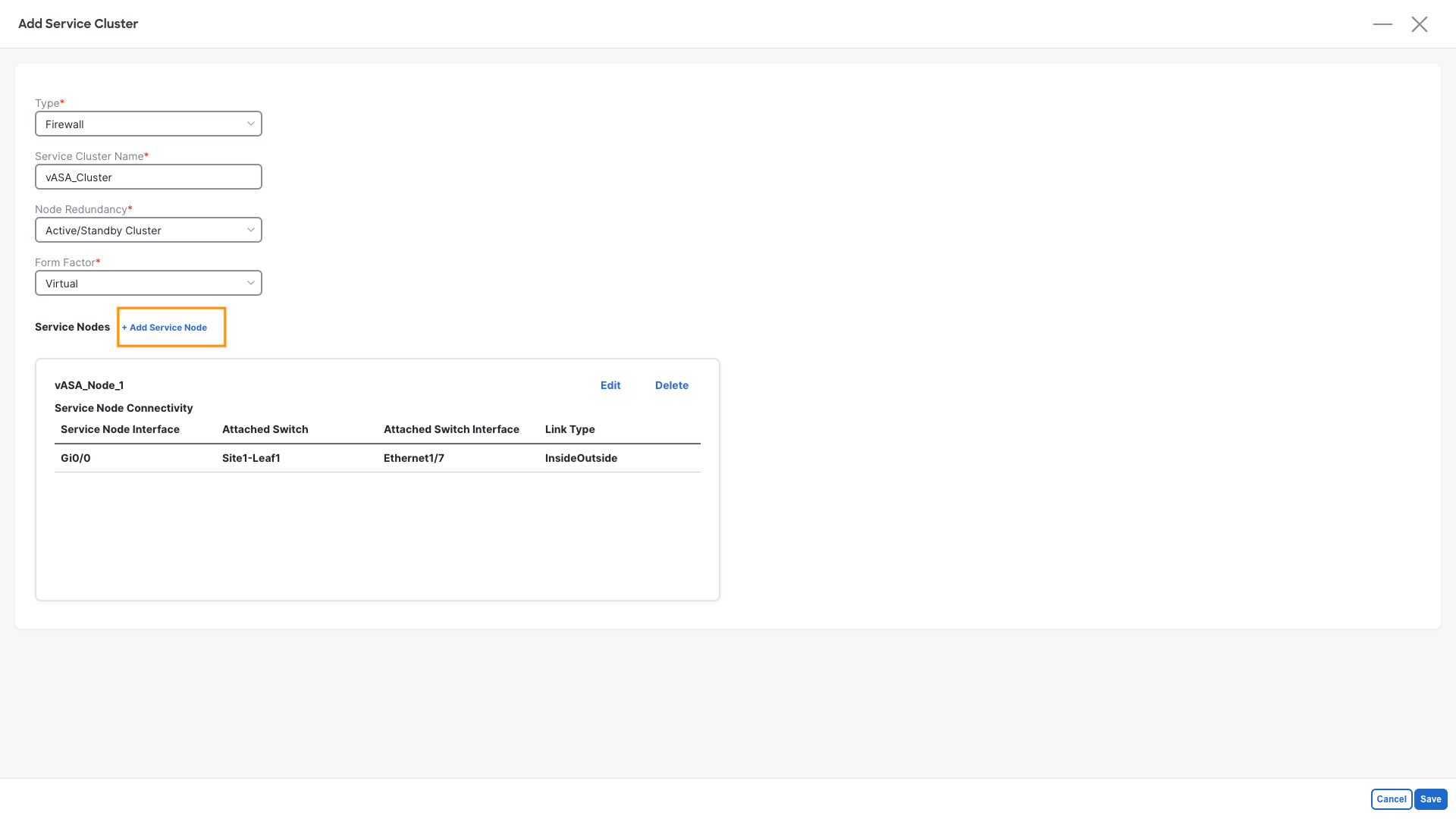
Step 7: Review the cluster definition
- Your cluster should now be defined as per below image
- Click on Save
Service Function
The service function is our second step. It is required in order to tell NDFC how the fabric should speak with the firewall.
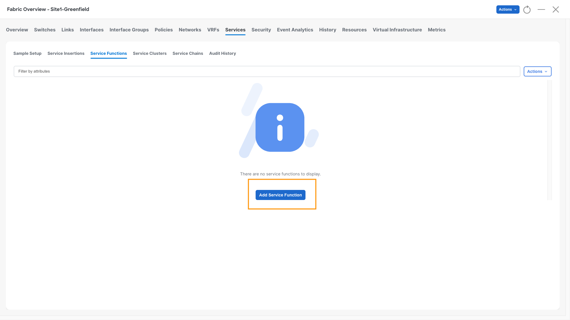
Step 1: Define the Service Function
- Click on Service Functions
- Click on Add Service Function
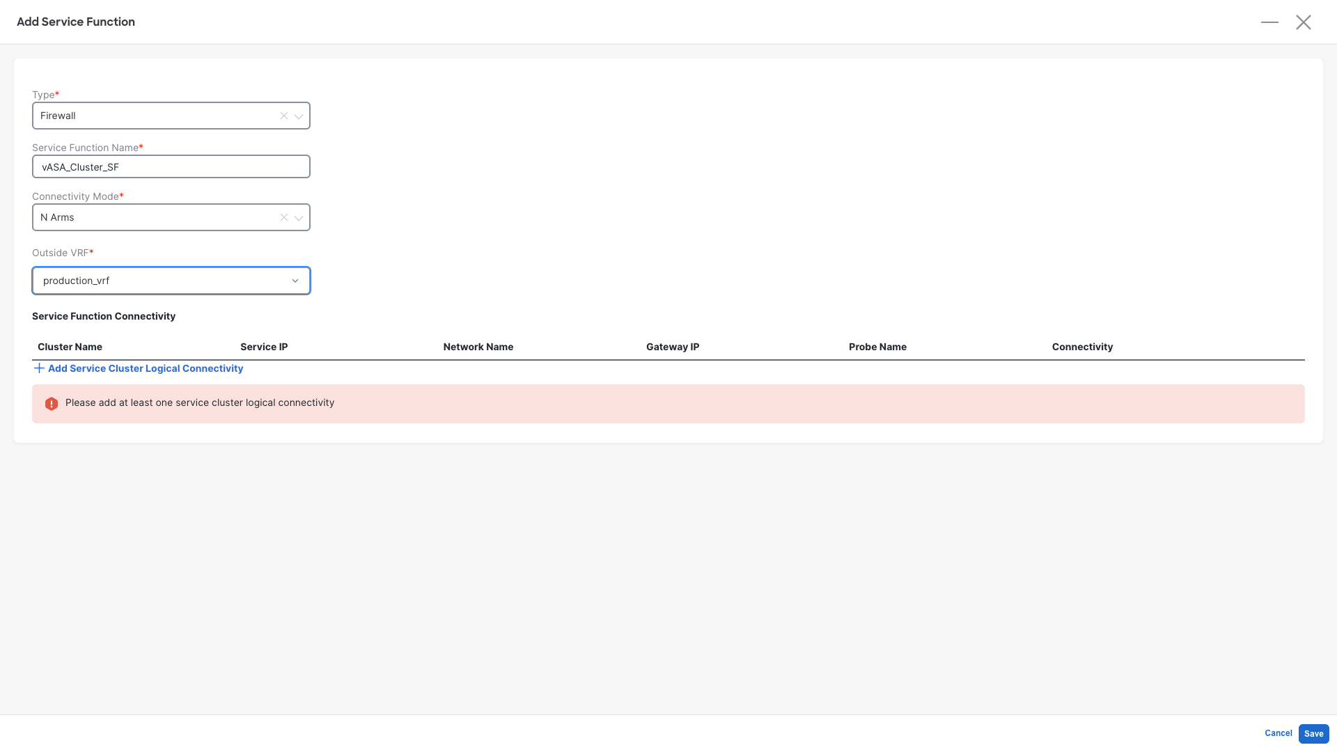
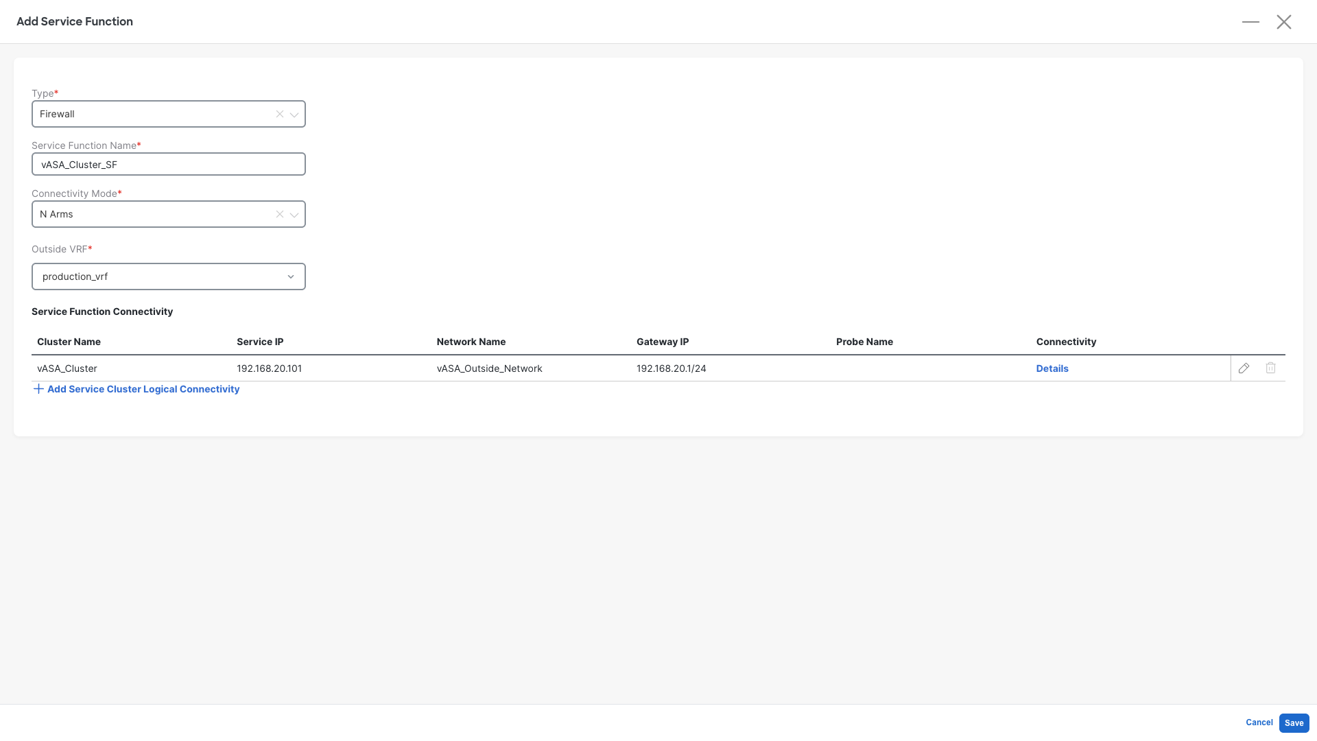
Step 2: Define the Service Function properties:
- Type: Firewall
- Service Cluster Name: vASA_Cluster_SF
- Connectivity Mode: N Arms
- Outside VRF: production_vrf
- Click on +Add Service Cluster Logical Connectivity
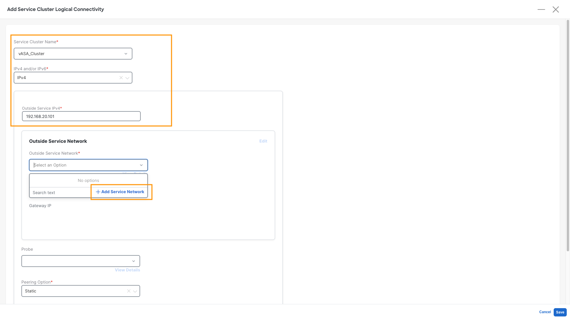
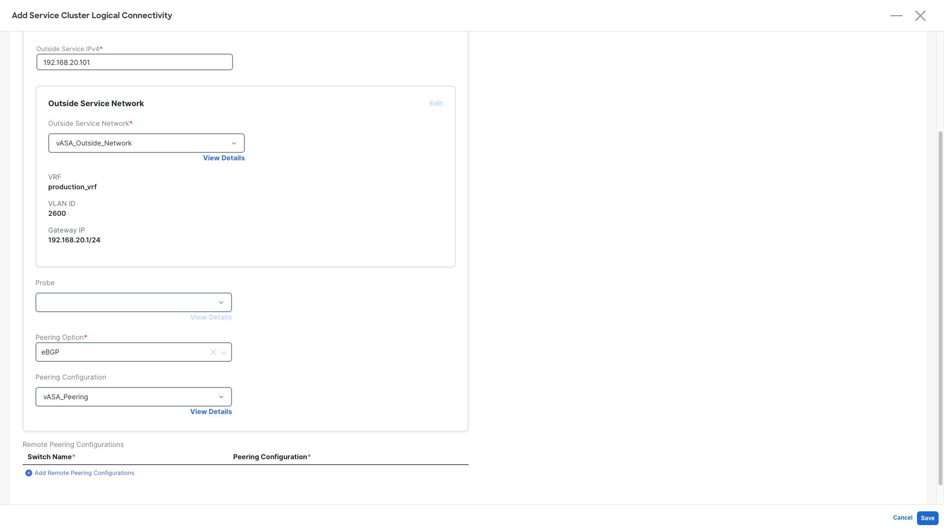
Step 3: Define the Service Function Logical Connectivity - Part 1:
- Service Cluster Name : vASA_Cluster - This is the one we created earlier
- IPv4 and/or IPv6: IPv4
- Outside Service IPv4: 192.168.20.101 - This is the Firewall IP configured on it's external interface
- Outside Service Network: Click on Add Service Network
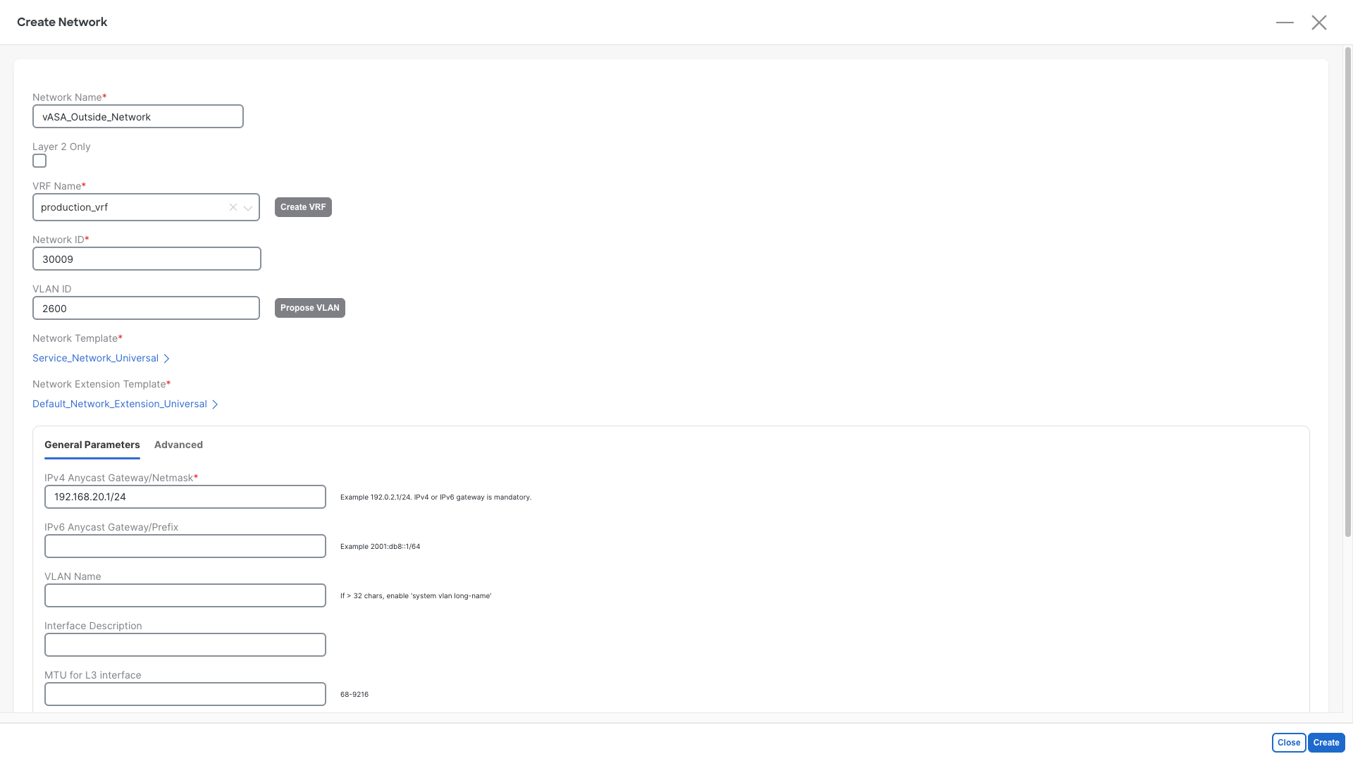
Step 4: Add Service Network:
- Network Name : vASA_Outside_Network
- VRF Name: production_vrf
- Network ID: Any provided value is ok
- VLAN ID: 2600
- IPv4 Anycast Gateway/Netmask: 192.168.20.1/24
- Click on Create
Warning
Do not use a different VLAN or different IP address value or the firewall will discard the packets
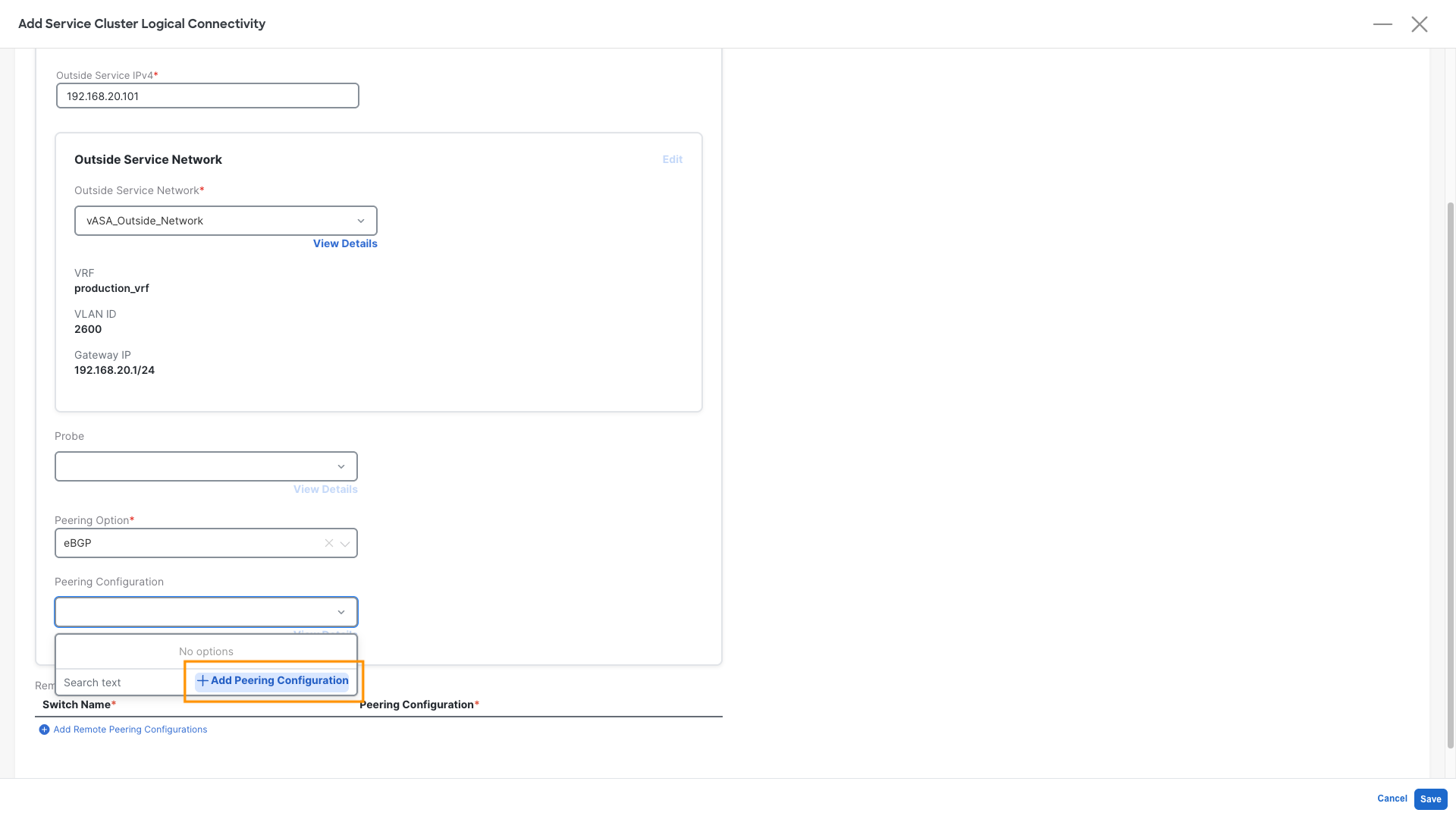
Step 5: Define the Service Function Logical Connectivity - Part 2:
Now that we have defined the transit network between firewall and fabric we can scroll down and continue
- Probe : Leave it empty, it is not required for this use case, but can be used for other deployment models
- Peering Option: Select eBGP
- Peering Configuration: Click on Add Peering Configuration
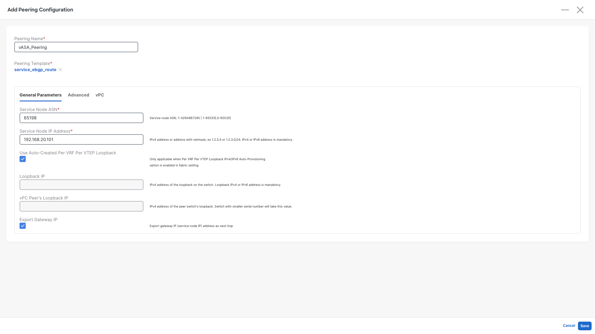
Step 6: Define the Firewall Peering Configuration
- Peering Name : vASA_Peering
- Service Node ASN: Select 65198
- Service Node IP Address: 192.168.20.101
- Check the Use Auto-Created Per VRF Per VTEP Loopback -- This will tell NDFC to use the loopbacks we have configured earlier to form BGP peering
- Check the Export Gateway IP
- Click on Save
What is this Export Gateway IP?
Export Gateway IP enables the recursive lookup of the external prefixes advertised by the firewall. Those EVPN Routes will contain the IP address of the firewall. Remote VTEPs will only send the traffic to the leaf where the active firewall is attached. By not selecting this the traffic will be sent to all the leaves who have an eBGP session with the Firewall, also the ones where the firewall is not active. And that would cause a partial traffic blackhole.
Step 7: Save the Service Cluster Logical Connectivity:
- Click on Save
Step 8: Save the Service Function:
- Click on Save
Service Insertion
The service Insertion is our third step. It is required in order to tell NDFC what is the overall traffic redirection method we want to achieve and to glue all the previous configurations together.
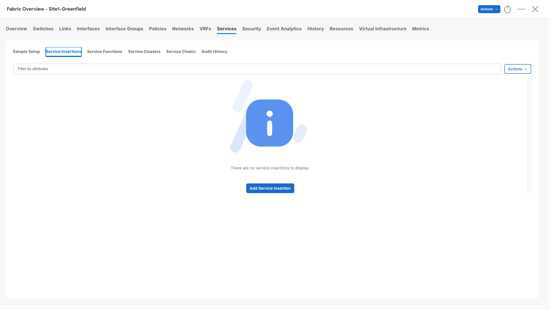
Step 1: Define the Service Insertion:
- Click on Service Insertions
- Click on Add Service Insertion
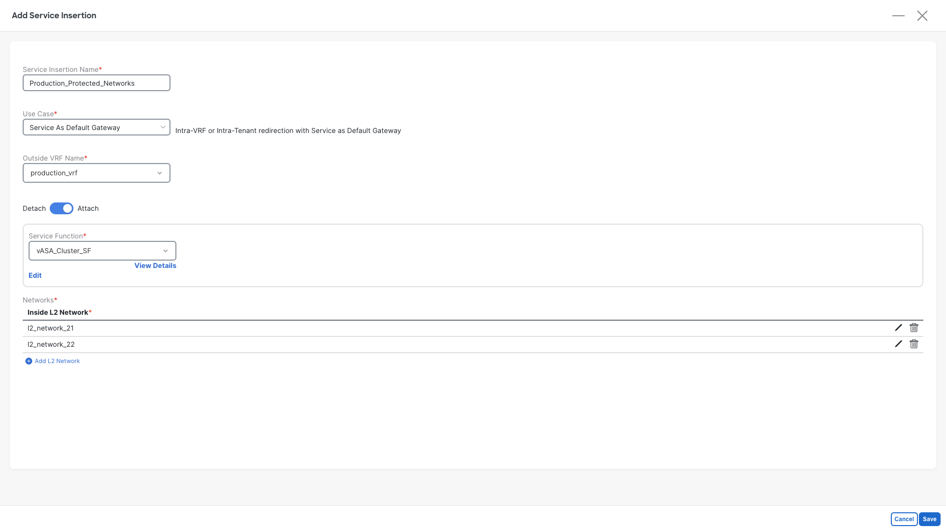
Step 2: Define the Service Insertion properties:
- Service Insertion Name: Production_Protected_Networks
- Use Case: Service As Default Gateway
- Outside VRF Name: production_vrf
- Move the slider to Attach
- Service Function: Select vASA_Cluster_SF
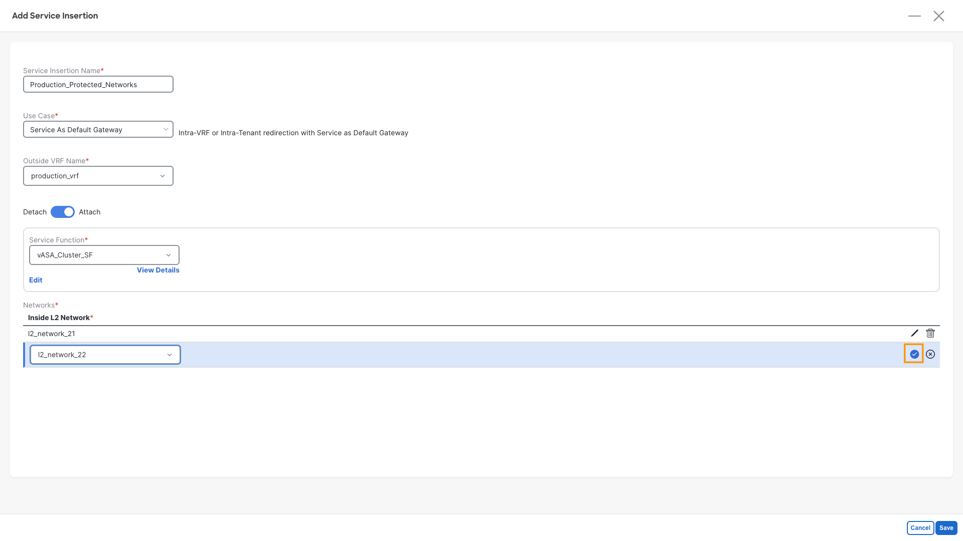
- Add the L2 Networks that were created with Ansible, repeat this for both networks
- Click on Add L2 Network
- Select l2_network_2X (l2_network_21 & l2_network_22)
- Click on the confirm checkbox
- Click on Save
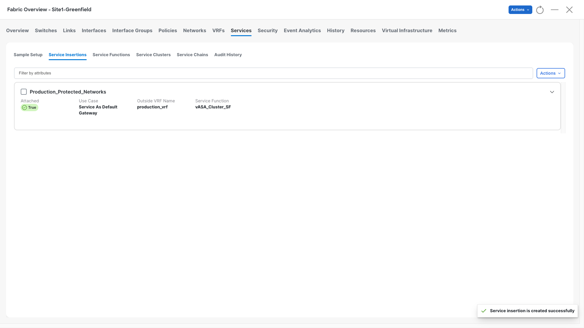
Step 3: Check the Confirmation Pop-Up
- NDFC should raise a pop-up saying Service insertion is created successfully, that means that configurations are complete and correct
Step 4: Recalculate and Deploy
- At this point we can render the entire worflow and push the configurations where required
- Perform a Recalculate and Deploy operation in Site1-Greenfield
- Observe all the configurations that are being added to Site1-Leaf1 and Site1-Leaf2
Verification - Check the fabric Status and the traffic flow
Check BGP Status
Step 1: Access Site1-Leaf1
- Open the MTPutty terminal:
- Double-click on Site1-Leaf1
- Run the following commands and check the result:
Site1-Leaf1
show bgp ipv4 unicast summary vrf production_vrf
show bgp ipv4 unicast neighbor 192.168.20.101 routes vrf production_vrf
eBGP active on a single Leaf
eBGP Session will be active on the leaf attached to the active firewall. This is due to a limitation in the Nexus 9000 virtual platform
It will not have any impact on your lab
Step 2: Observe the results
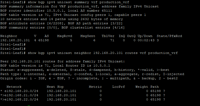
- Notice how the leaf established the eBPG session with the firewall
- Over this session the leaf is receiving three prefixes, which are the firewall direct networks
192.168.20.0 not installed
192.168.20.0/24 is not installed from BGP as the leaf has that network directly connected and is the transit VLAN between the fabric and the firewall.
Check that traffic is flowing
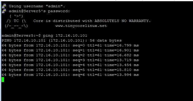
Step 1: Access Server5
- Open the MTPutty terminal:
- Double-click on Server5
- Run the following commands and check the result:
Server5
ping 192.168.22.101
ping 172.16.10.101
Step 2: Observe the results, you should be able to reach the above two networks and all traffic is getting forwarded via the active firewall
You can continue now with the final Task #8