Task 1 - Deploy a VXLAN EVPN Greenfield Fabric
Overview
In this section, we will create a fabric named Site1-Greenfield and deploy all the required configurations for a VXLAN BGP EVPN network using NDFC. NDFC clears all configurations on the switches except for management before pushing the VXLAN EVPN configurations onto them. The first Day-0 step in NDFC's lifecycle management of your Greenfield fabric is to create the fabric where you define the fabric settings such as:
- BGP ASN
- Replication mode for Overlay BUM (Broadcast, Unknown Unicast, and Multicast)
- Underlay IGP parameters
- Resources that will be used for allocating IP addresses, VLANs, VNIs, etc.
- Other settings
You can configure the fabric using a powerful, flexible, and customizable template-based framework. With minimal user input, you can bring up an entire fabric with Cisco-recommended best practice configurations in very little time. The set of parameters exposed when creating a fabric in the Fabric Settings allows you to tailor the fabric to their preferred underlay provisioning options.
Creating a Greenfield Fabric
Step 1 - Double-click the Chrome shortcut on the wkst1 desktop and on the Nexus Dashboard logon screen, login with the credentials admin/C1sco12345
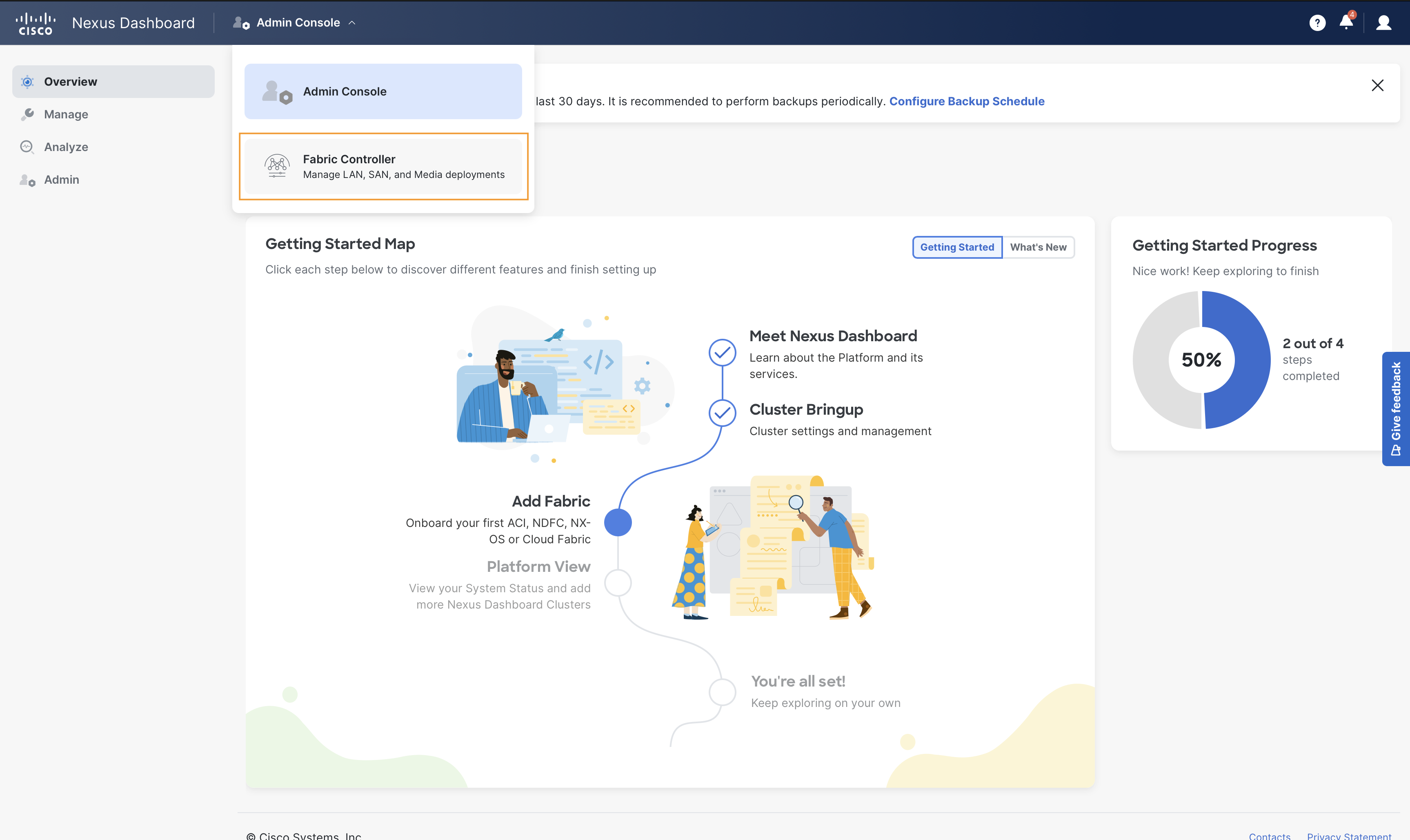
Click on the Admin Console dropdown and select Fabric Controller. This will take you to the Fabric Controller page of Nexus Dashboard
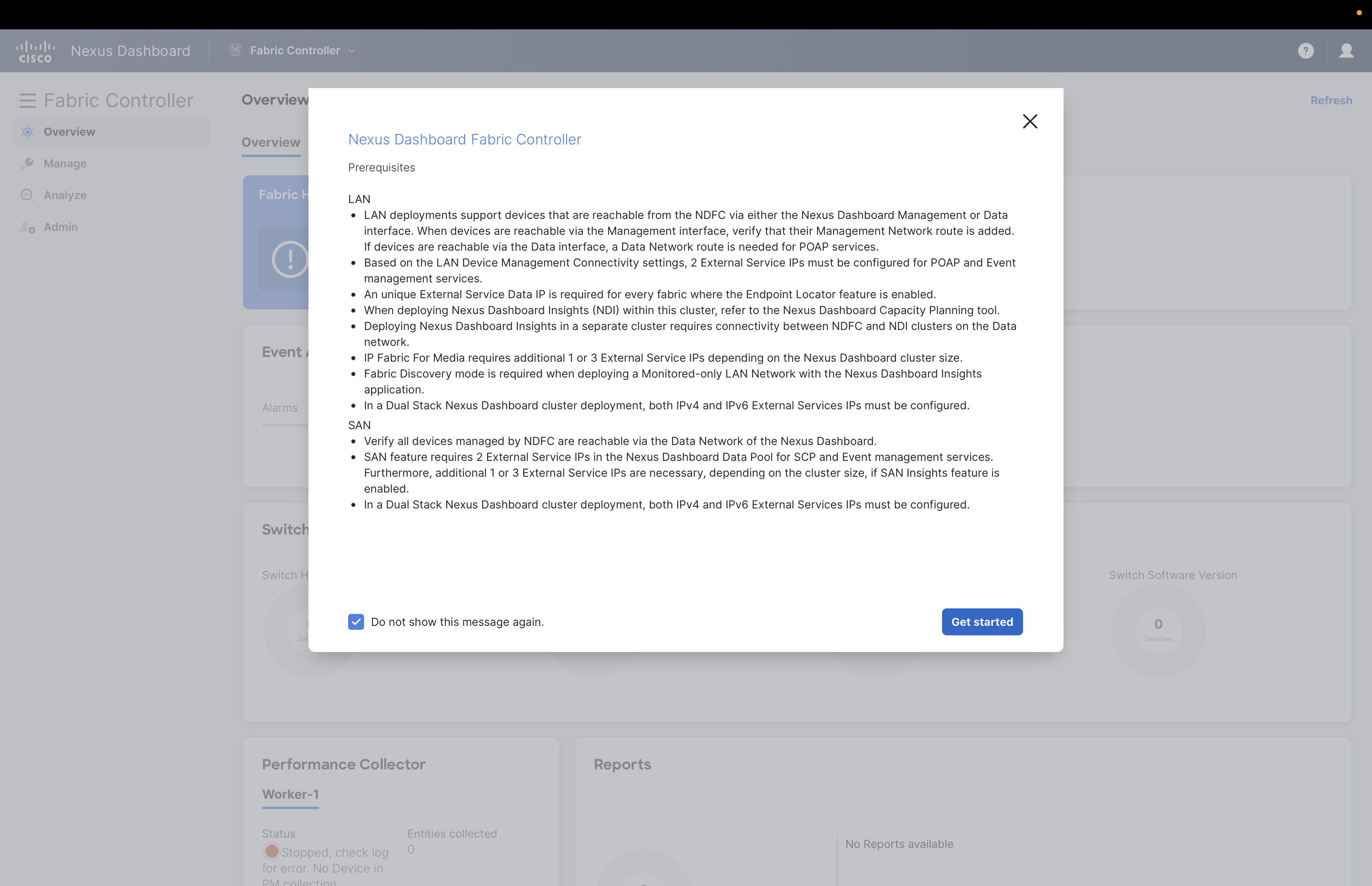
You might see Prerequisites dialog box popping up, please select Do not show this message again check box and click on Get started button.
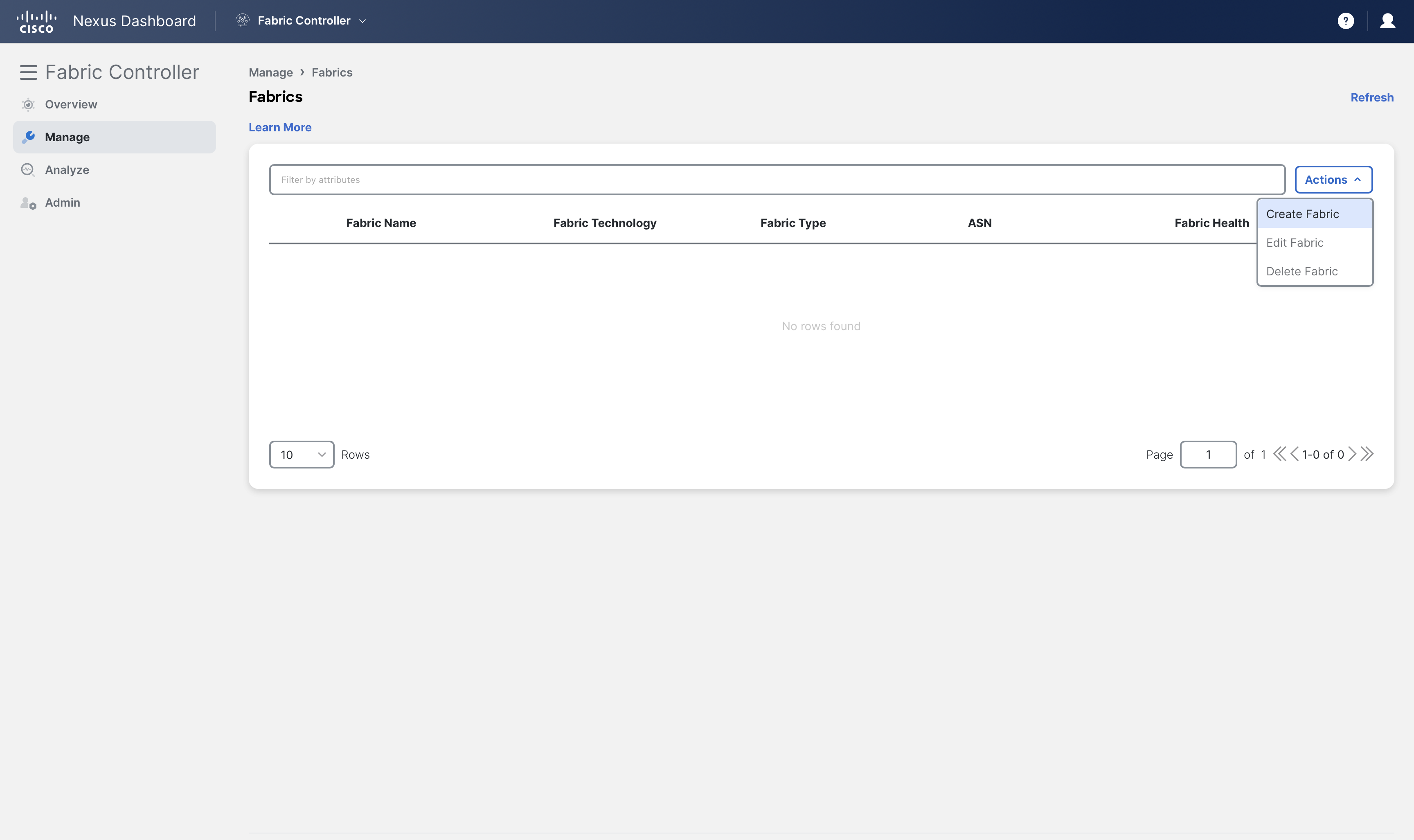
Step 2 - On Nexus Dashboard's Fabric Controller page, click Manage > Fabrics
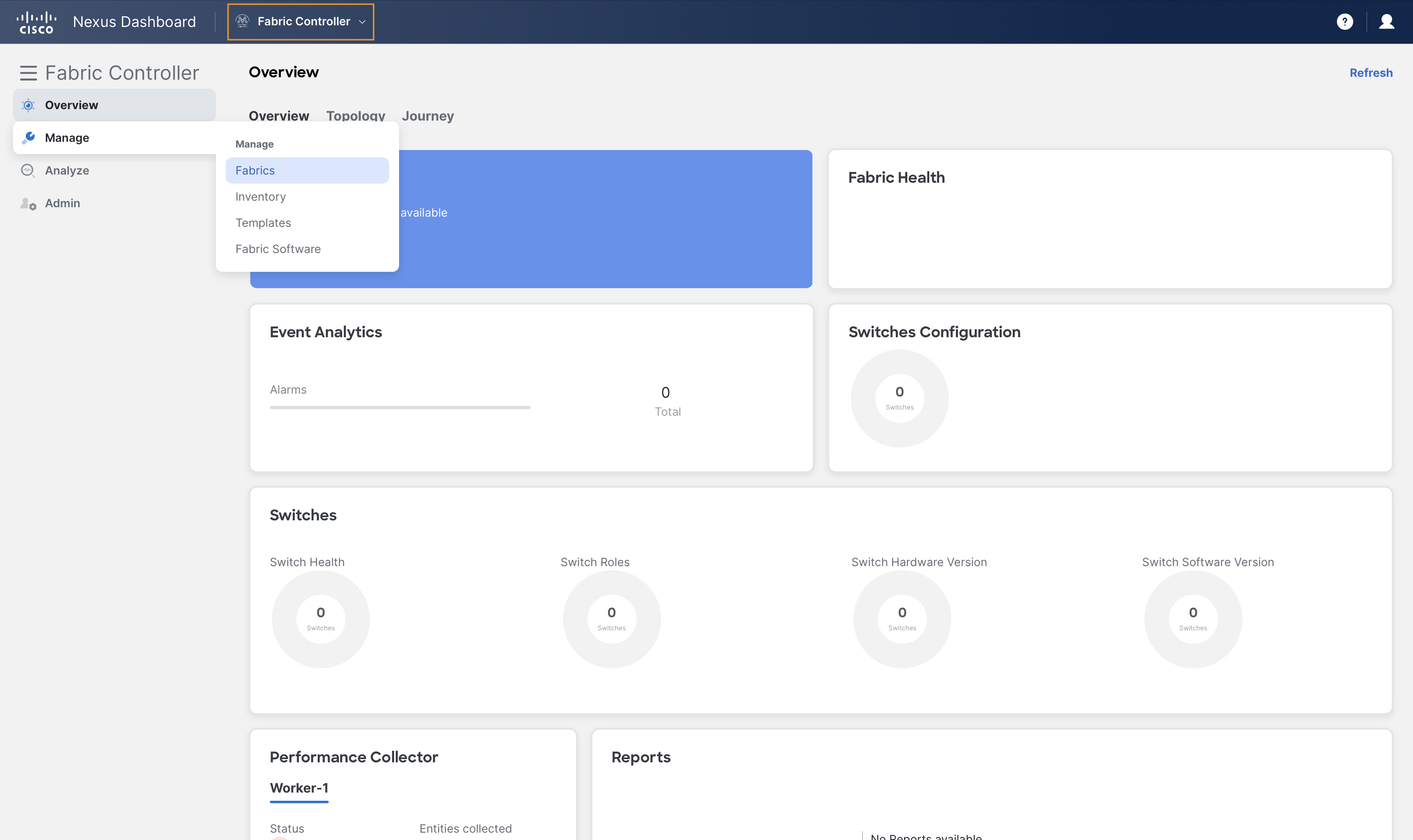
and then, click Create Fabric from Actions dropdown
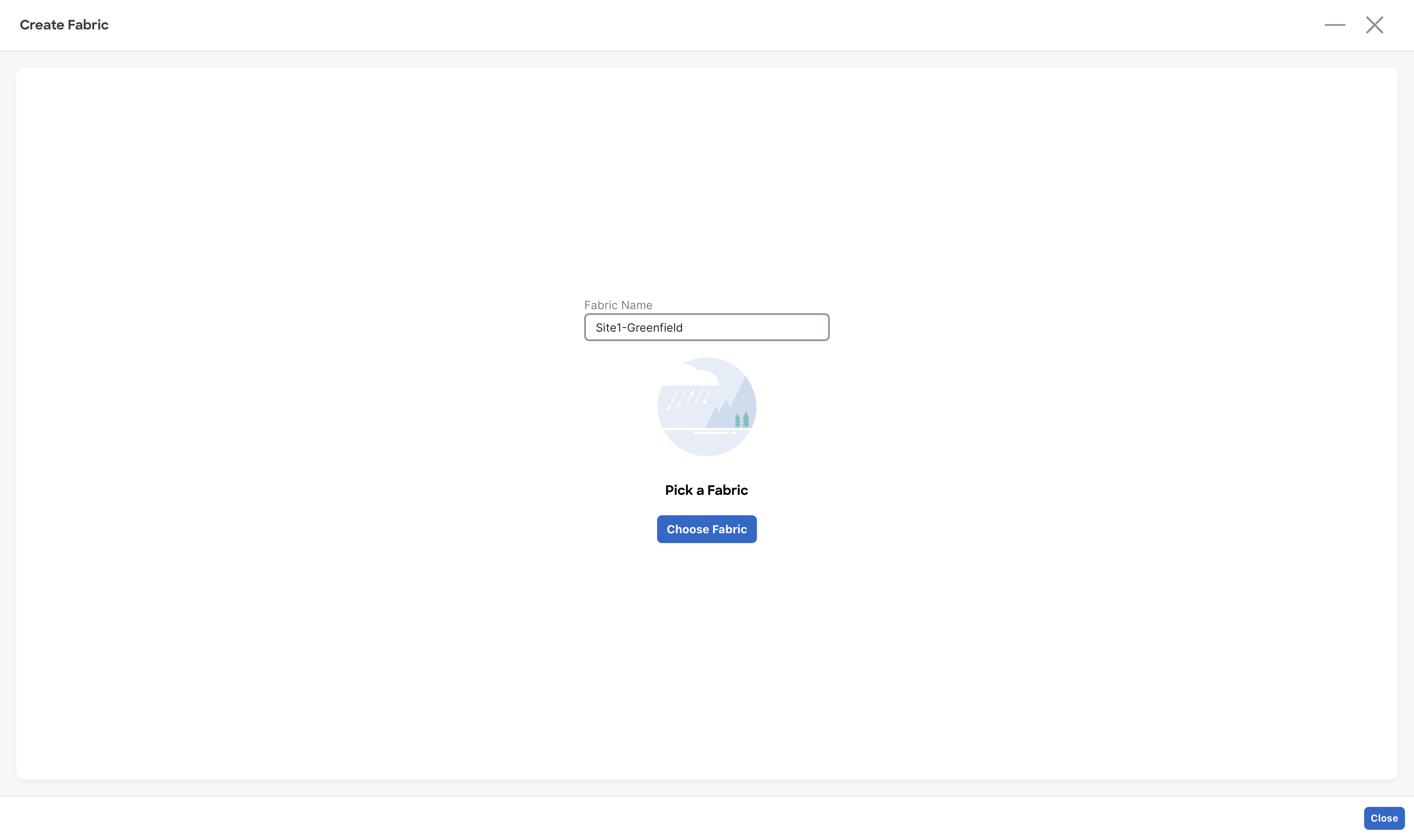
Step 3 - In the Fabric Name field, enter Site1-Greenfield and click Choose Fabric button
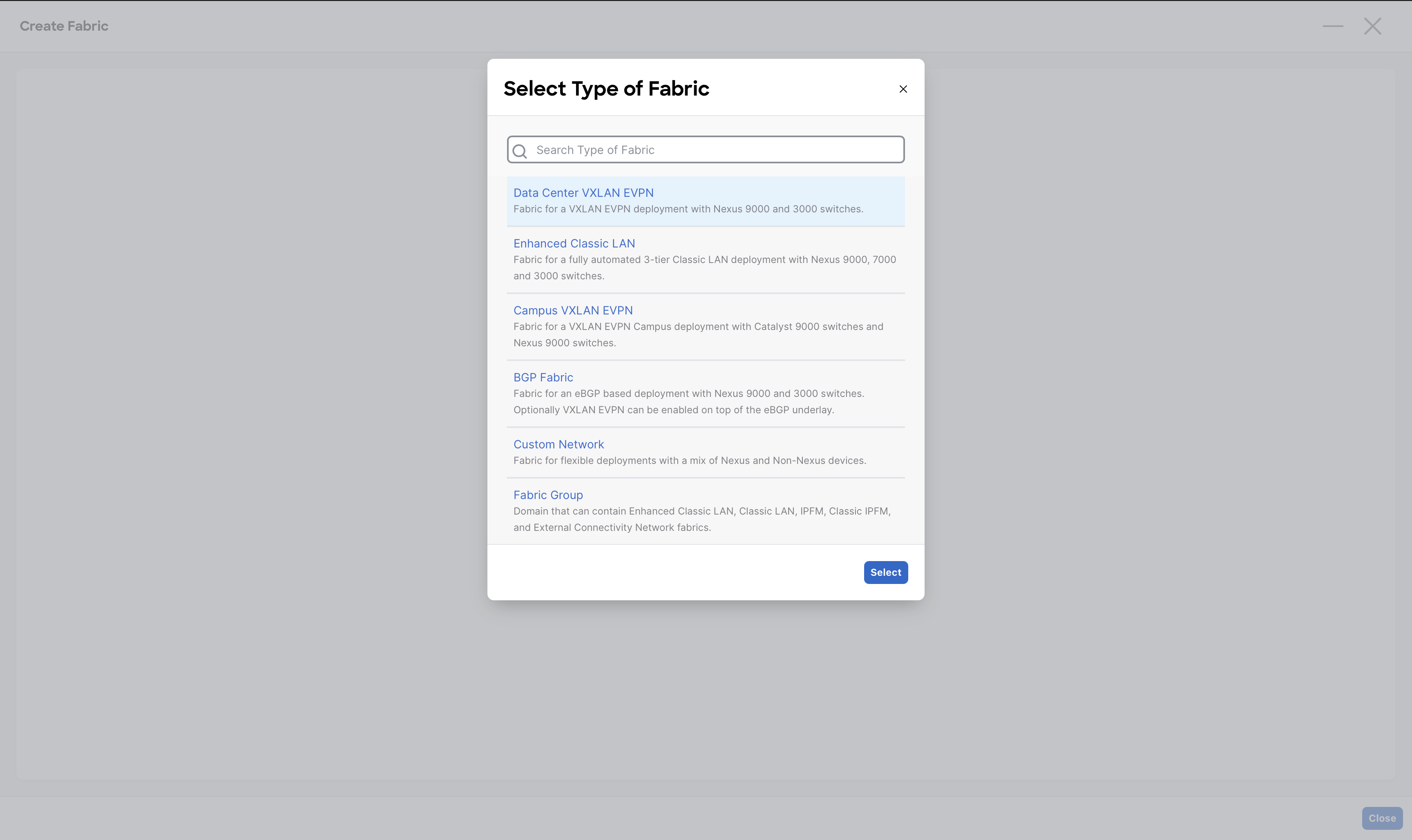
From the list of various fabric templates supported by NDFC, select the Data Center VXLAN EVPN fabric template and click on Select button
Note
As you can see, NDFC has many fabric templates thanks to its multi-architecture nature.
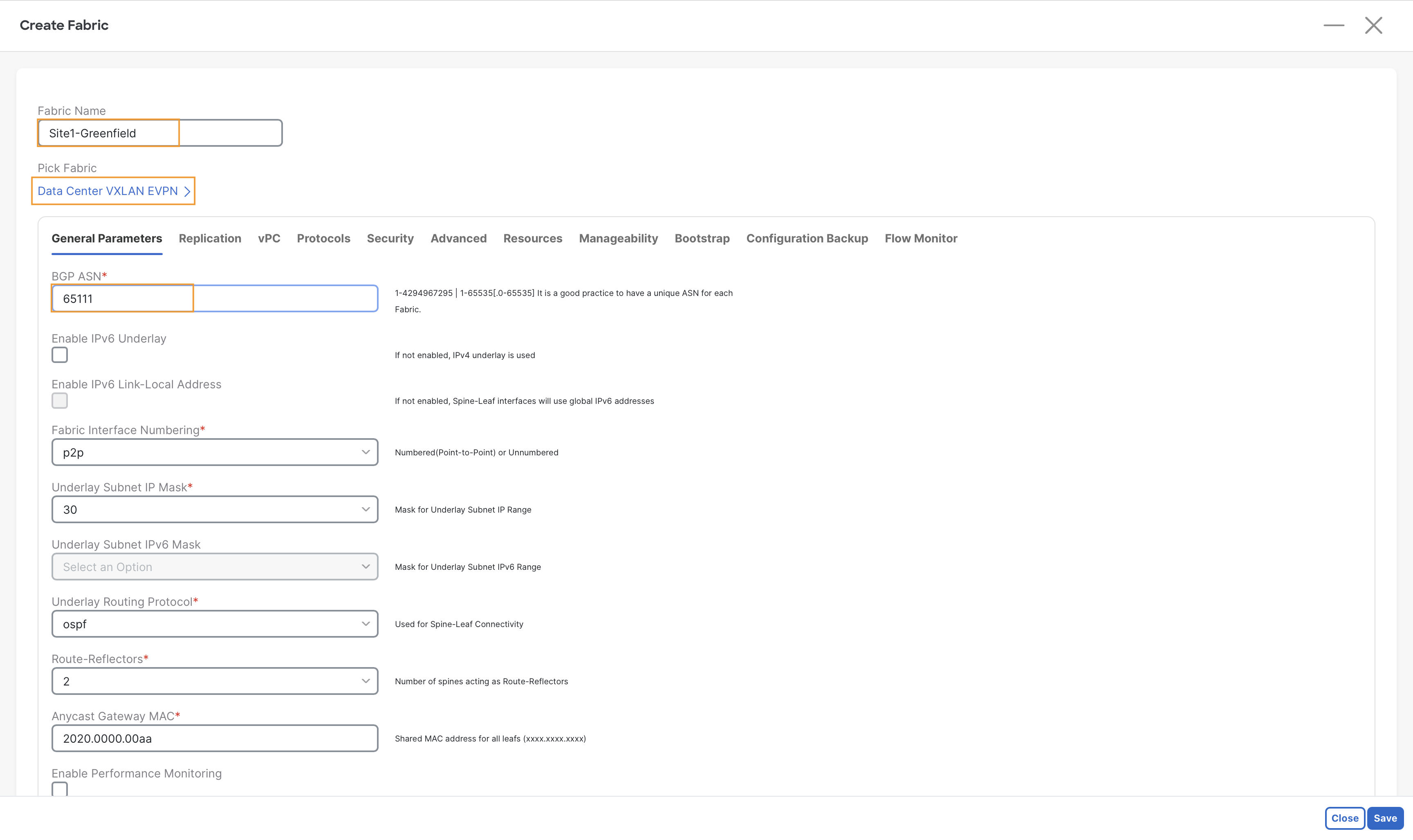
Step 4 - On the General Parameters tab under Create Fabric , enter 65111 in the BGP ASN field
Note
The remaining fields on this tab are pre-filled by NDFC and they could be changed if required. However, for this lab, we do not need to modify them. In a real deployment, ensure you understand and choose wisely all the different options.
Step 5 - Go to Advanced tab, and scroll down to Greenfield Cleanup Option and select Enable from the drop-down

This will save you time
When NDFC imports a device for a greenfield VXLAN EVPN Fabric, by default it will wipe all the existing configuration AND it will also reload the device. Changing the Greenfield Cleanup Option to Enable will avoid the reload.
Step 6 - (Optional) Observe the default IP ranges provided by NDFC for building this fabric, we do not need to change them.
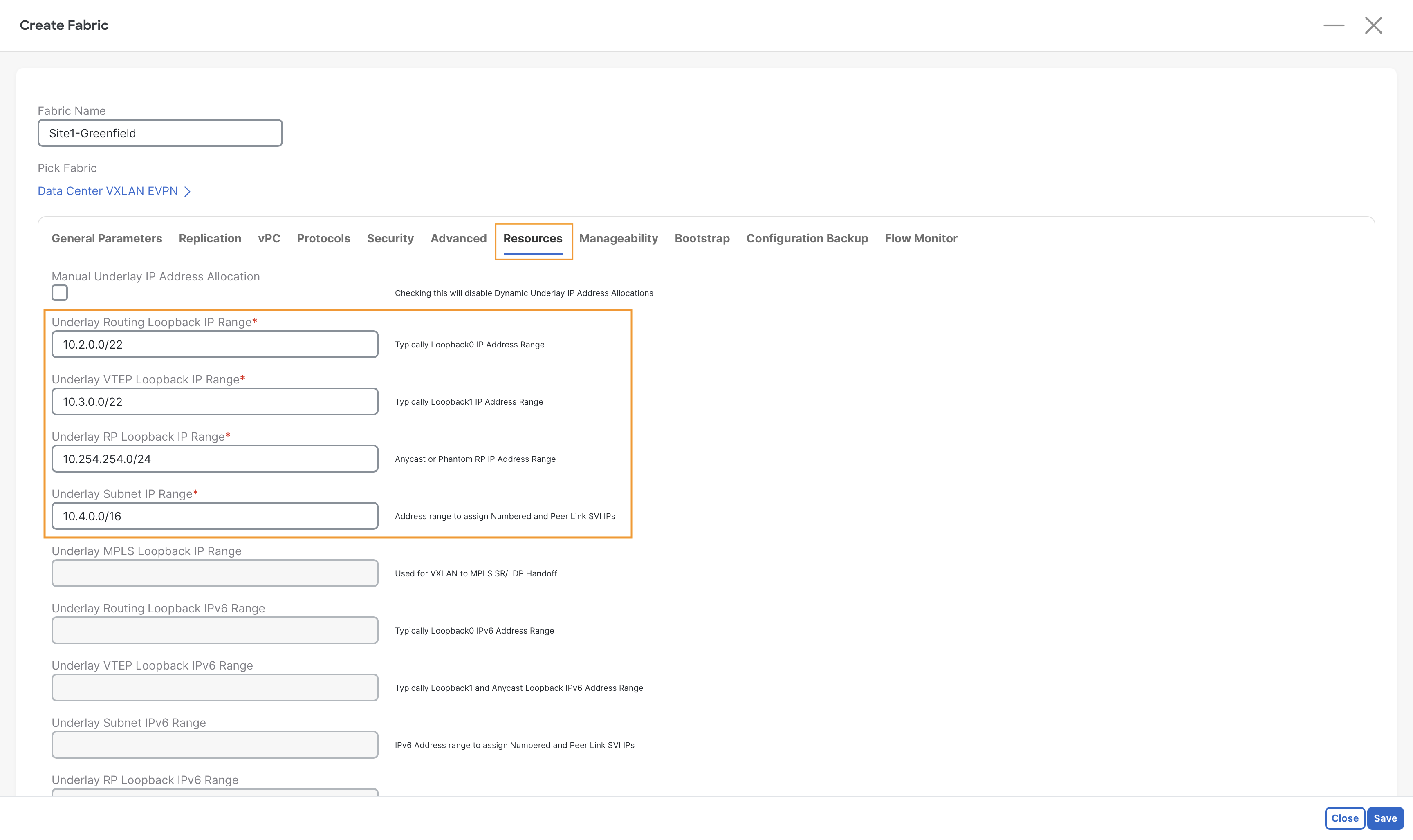
Info
These are the major subnets that NDFC will use to allocate the IP addresses for the interfaces that will be automatically configured. These are all the required loopback and eventually the Point-to-Point interfaces between Spines and Leaves.
Step 7 - On the bottom right, click Save to create the fabric.
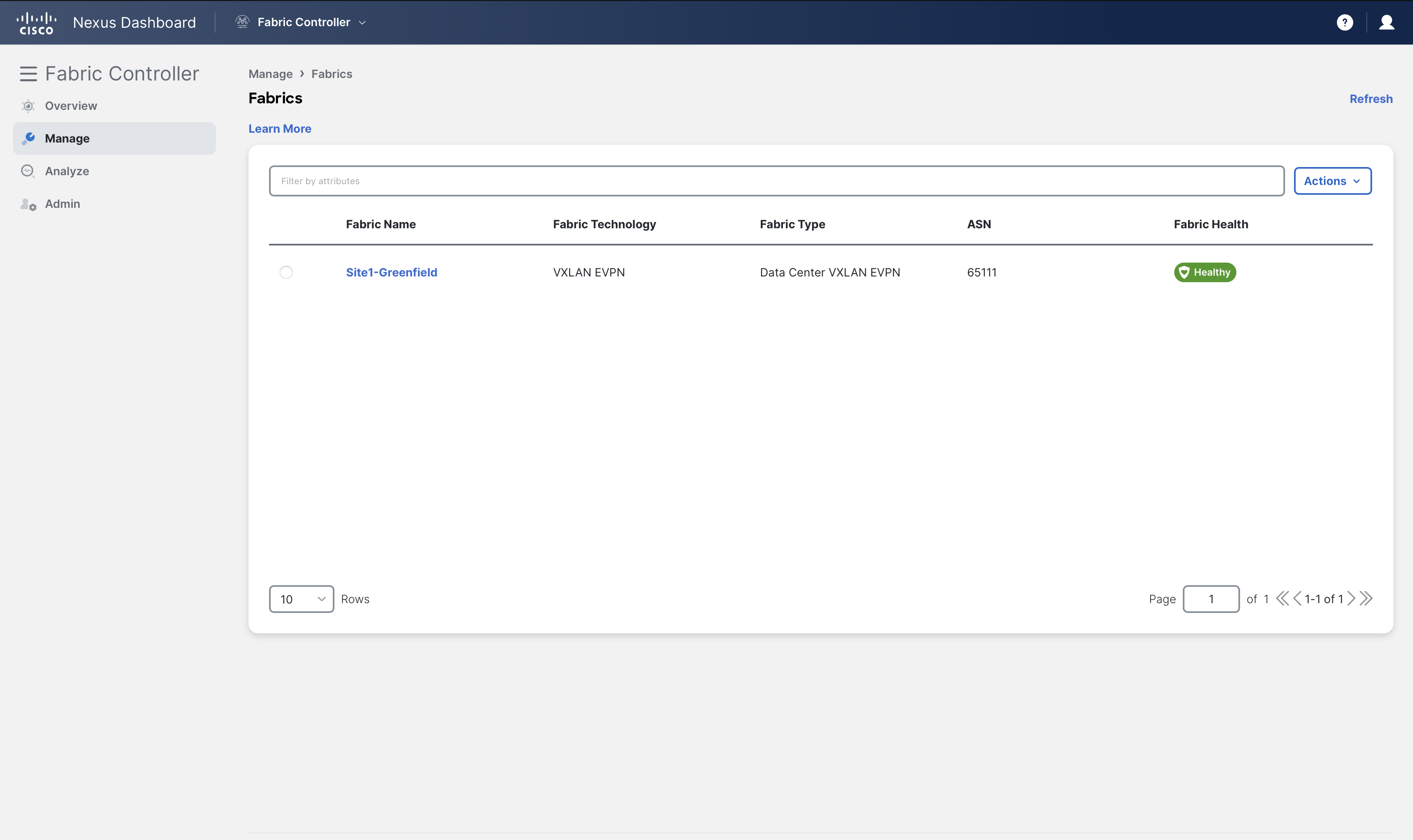
You can now see the Site1-Greenfield VXLAN fabric created under Manage > Fabrics
Adding Switches to the Fabric
Once a fabric is defined, the next step in the Day-0 lifecycle for NDFC fabrics is to discover and import the switches that will form the fabric. The switch discovery and import process can be done in either of two ways:
- Bootstrapping new switches with POAP
- Using a seed IP address of a switch in the fabric
For the first option, if NDFC is configured to do so it can act as a DHCP and/or POAP (Power-On Auto Provisioning) server for bootstrapping the devices. Devices can be imported without requiring any kind of initial configuration.
The second option, which you will use for this lab, is applicable for both Greenfield and Brownfield fabrics. In this case, an IP address for the mgmt0 interface must already be configured and reachable from NDFC. (NDFC also supports in-band management, but that is not covered today)
In a CLOS fabric, the majority of the switches are at an equal distance from each other, thus any of the switch in your fabric can be selected as the initial seed device. NDFC lets you define an expected hop-count to reach all its neighbors (hop count = 1), or the neighbors of the neighbors (hop count =2), and so on (hop count >=3). This discovery occurs by giving NDFC access to the switch through the local admin user or AAA user. This user must be able to SSH to the switches, perform SNMPv3 queries, and run show commands. One of the show commands is for CDP to discover subsequent directly connected switches, not to exceed the specified hop-count during the discovery.
In this section, you will perform these steps to discover and import the switches in your Site1-Greenfield fabric.
Step 1 - On Fabric Controller page, click Manage > Fabrics and then double-click on Site1-Greenfield fabric
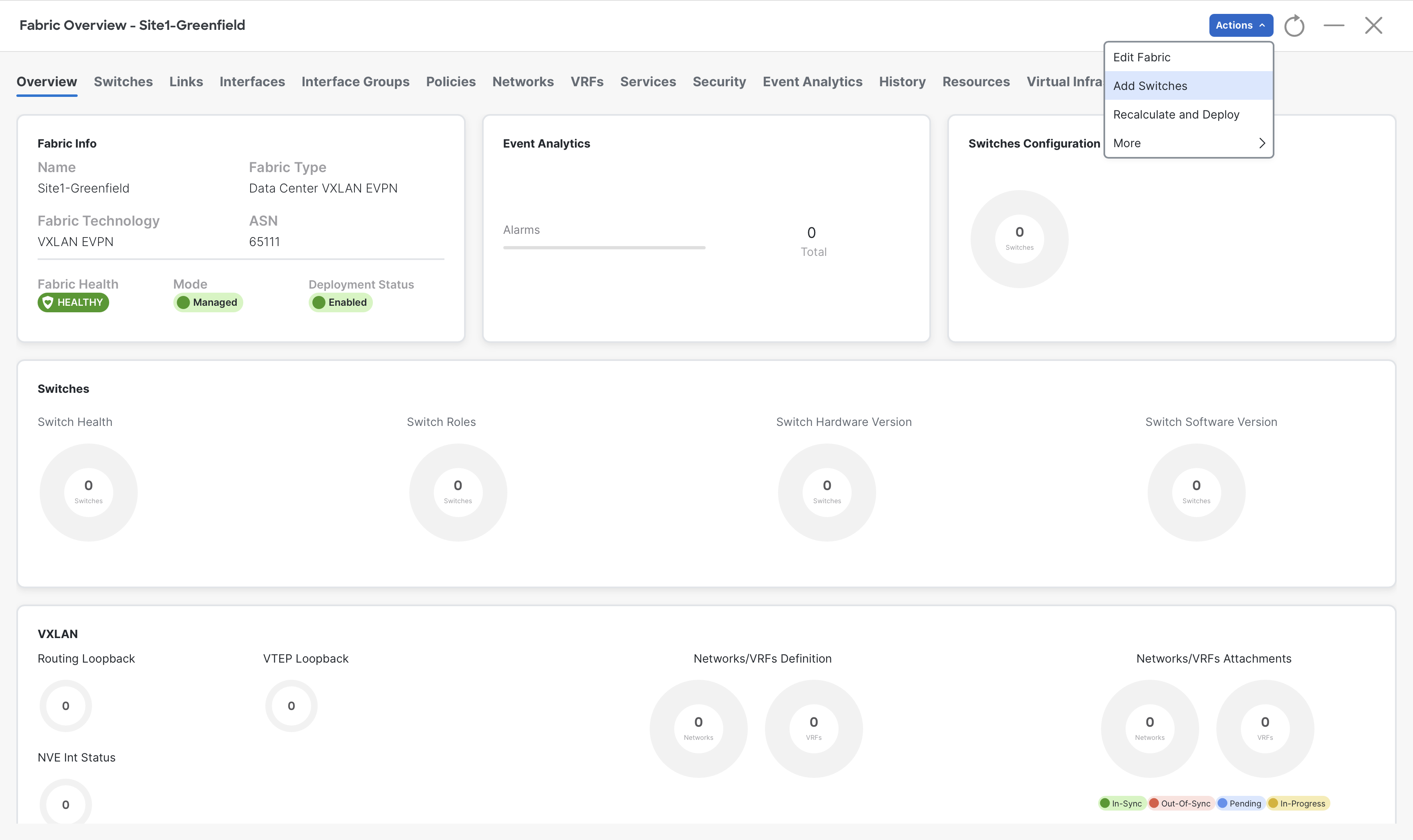
Step 2 - It will open up the detailed view of Site1-Greenfield fabric, and you will be taken to the Fabric Overview tab of Site1-Greenfield.
To add the devices to this fabric, click Actions > Add Switches
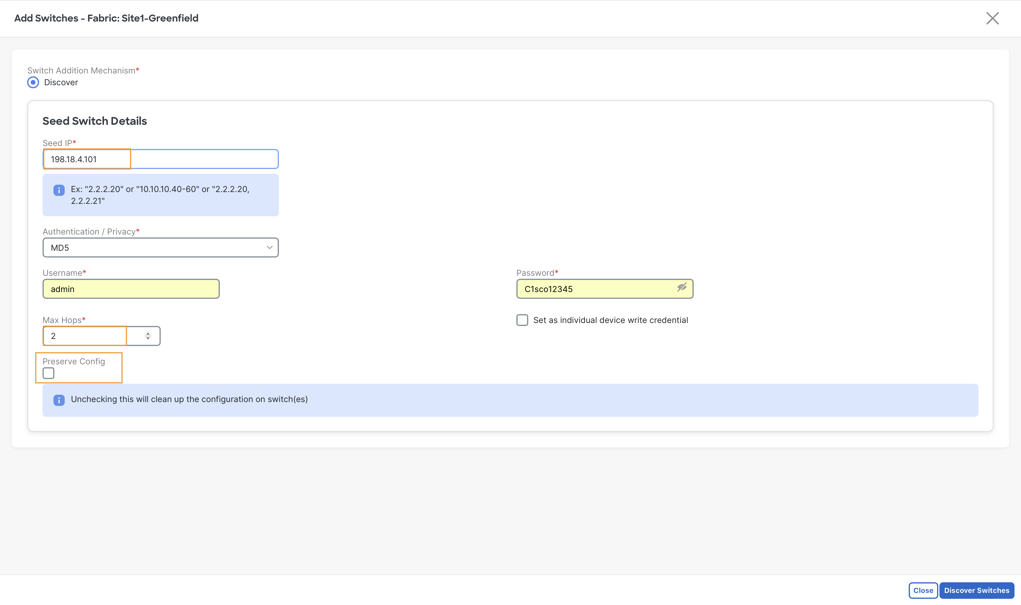
Step 3 - Provide the Seed switch details
- In the Seed IP field, enter 198.18.4.101
- In the Username field, enter admin
- In the Password field, enter C1sco12345
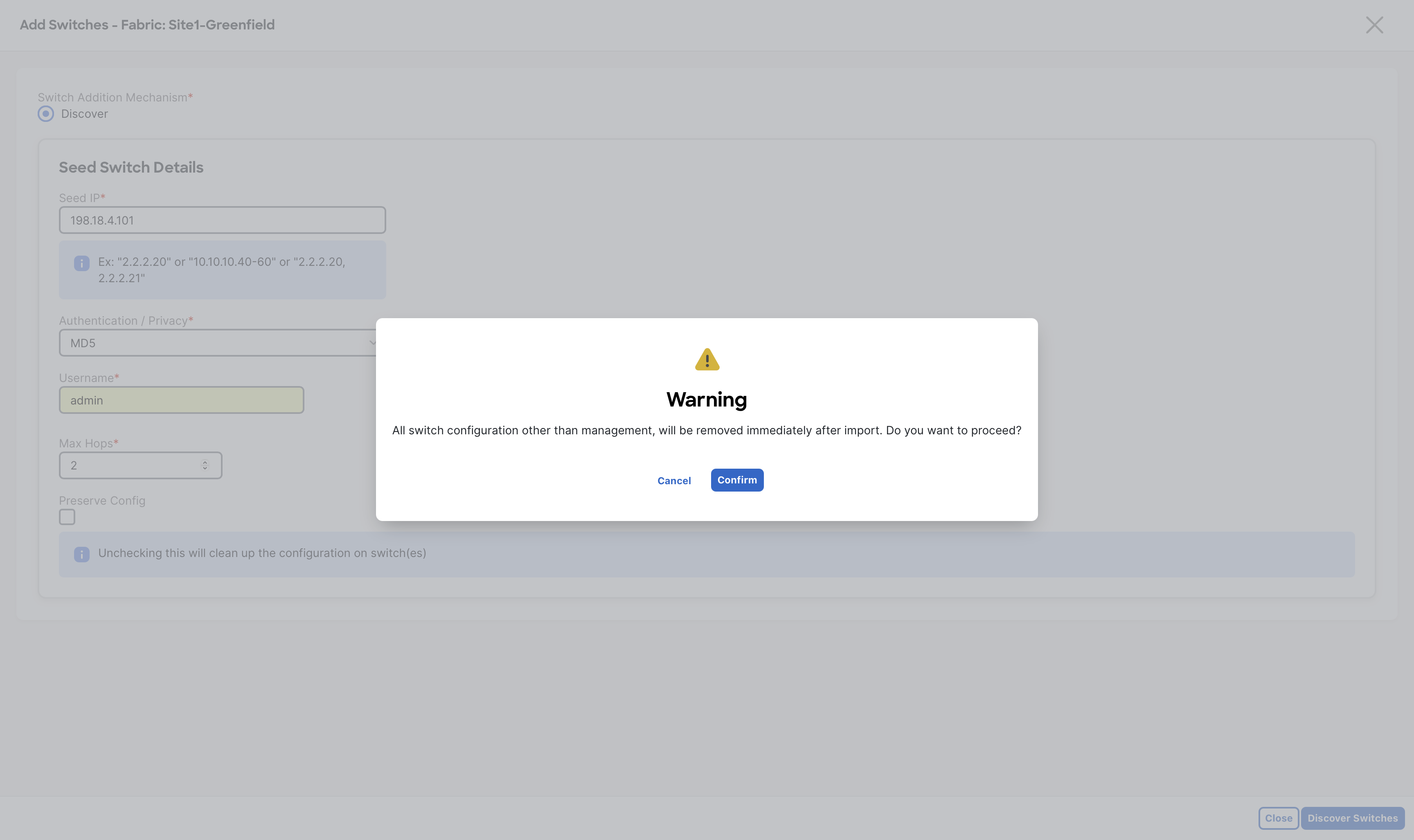
- Uncheck Preserve Config and then click Discover Switches
Warning
The Preserve Config must not be left checked here. This option must only be used when importing brownfield fabrics
Step 4 - A configuration removal warning message pops up as we have unchecked Preserve Config, click Confirm to proceed
Step 5 - On the next screen, NDFC will show up all the discovered devices based on the seed switch details provided.
Click the Select all check box to select all five switches from Site1 then click Add Switches
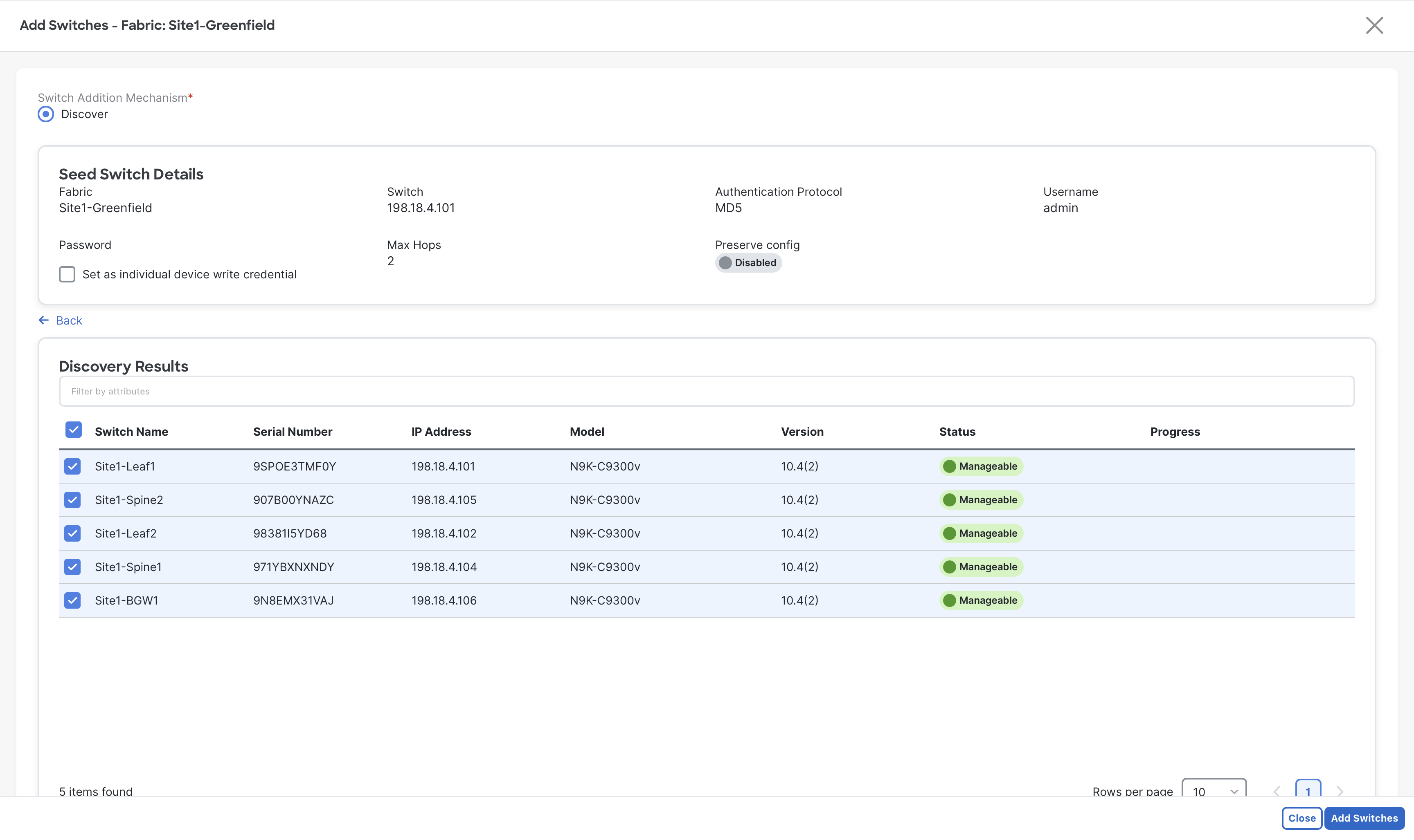
Be Patient
You are working with virtual nexus devices, this step might around 3 minutes, in a real scenario it will not take more than 30 seconds
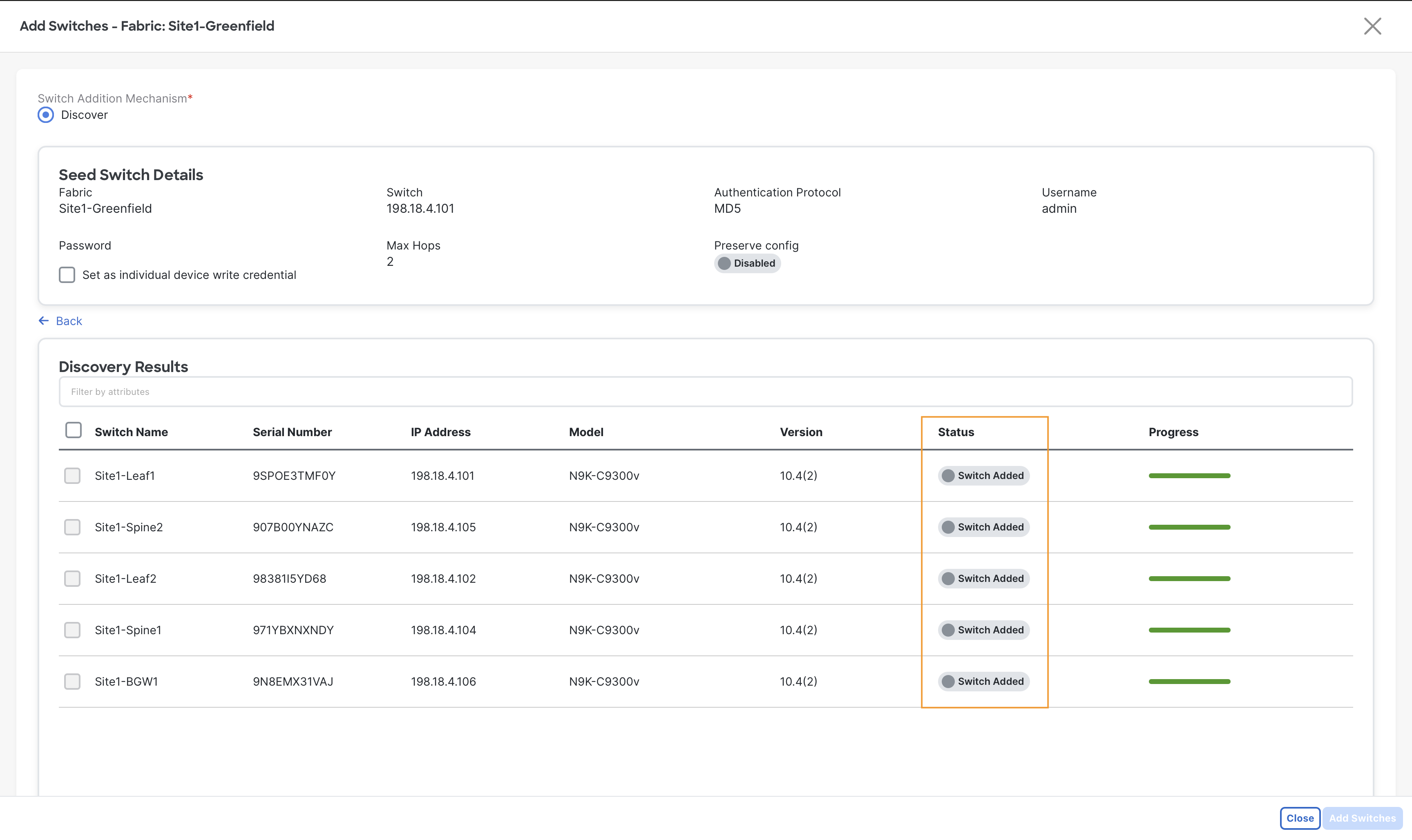
Step 6 - When the import completes you will notice the Status changed to Switch Added, now click Close
With the switches added to Site1-Greenfield fabric, the next Day-0 task is to ensure each switch has assumed the correct role in the fabric. The importance of role is to choose base templates which is rendered to generate the configuration and pushed to the switches by NDFC. As part of the built-in automation of the discovery and import, the system automatically assigns default roles based on the switch model.
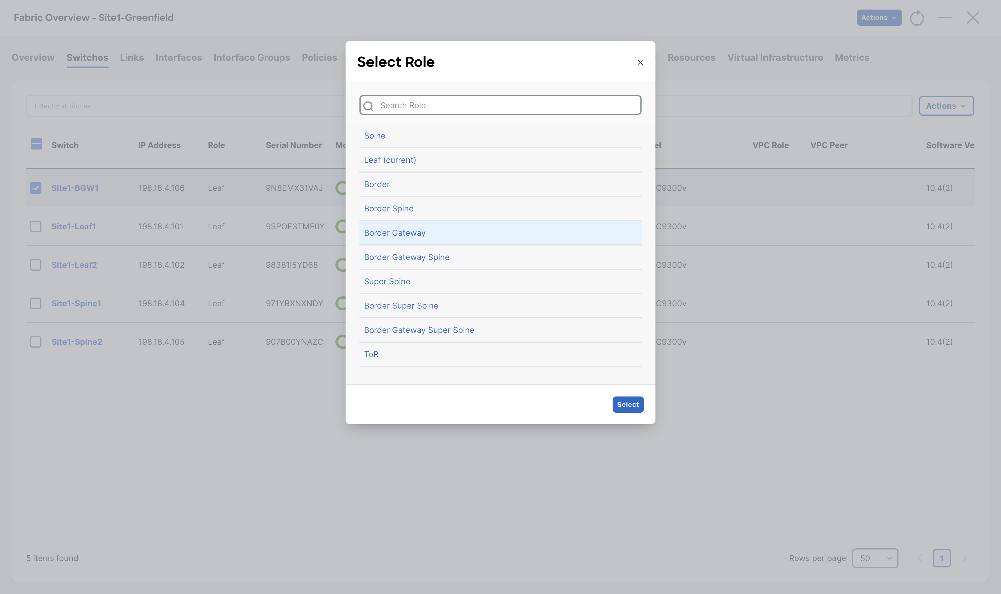
Step 7 - Go to the Switches tab of Site1-Greenfield fabric, select Site1-BGW1 switch and then click Actions > Set Role
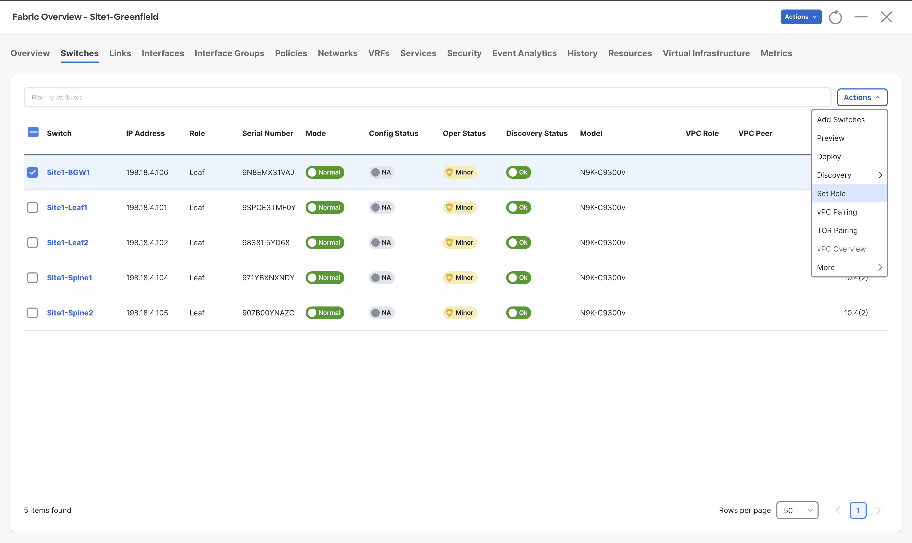
Step 8 - From the list of roles, choose Border Gateway role for Site1-BGW1 and then click Select
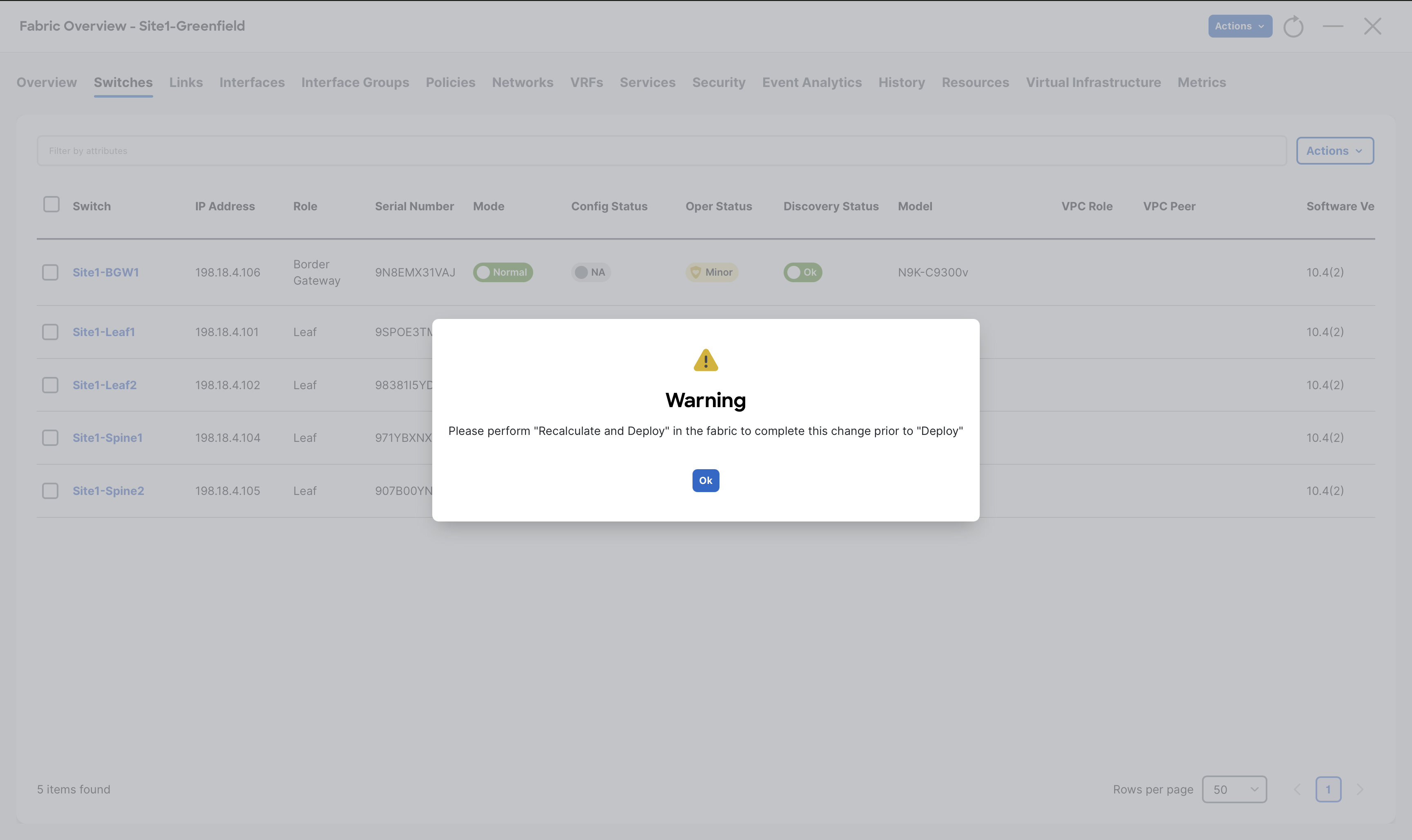
When you receive the warning message to perform Recalculate and Deploy, click Ok
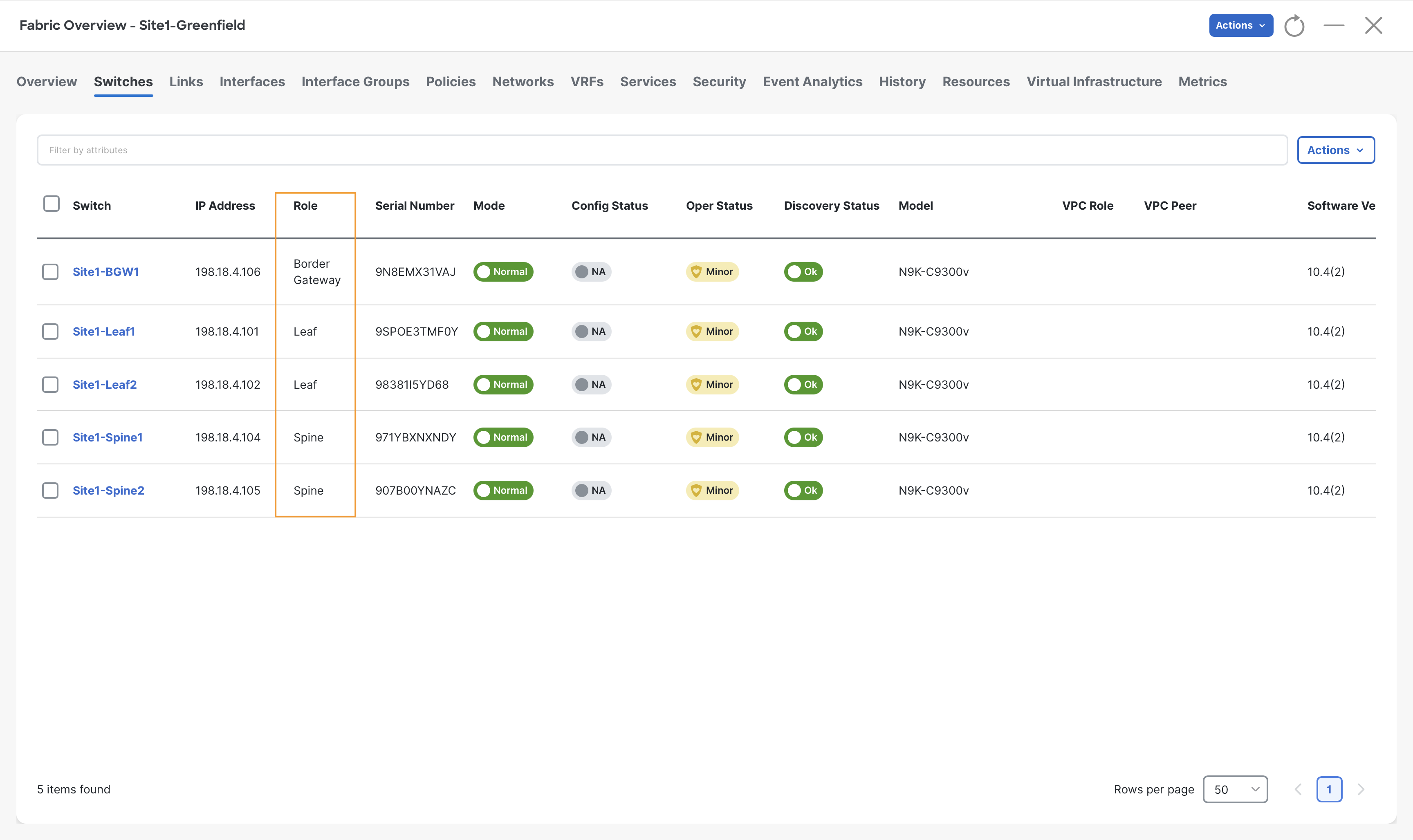
Step 9 - Repeat steps 7 & 8 for Site1-Spine1 and Site1-Spine2 switches and set their role to Spine
Step 10 - Observe the roles for all the switches
Configuring the vPC Domain
The last Day-0 task you perform for your Site1-Greenfield fabric is forming VPC domain using Site1-Leaf1 and Site1-Leaf2 switches.
From the Switches tab, you can create vPC domains by initially selecting only one of the switches in the pair. NDFC automatically detects its peer for you.
Step 1 - If you are not there already, from Fabric Controller page of Nexus Dashboard click Manage > Fabrics and double click on Site1-Greenfield fabric
Step 2 - Open the Switches tab and select Site1-Leaf1 switch and then click Actions > vPC pairing
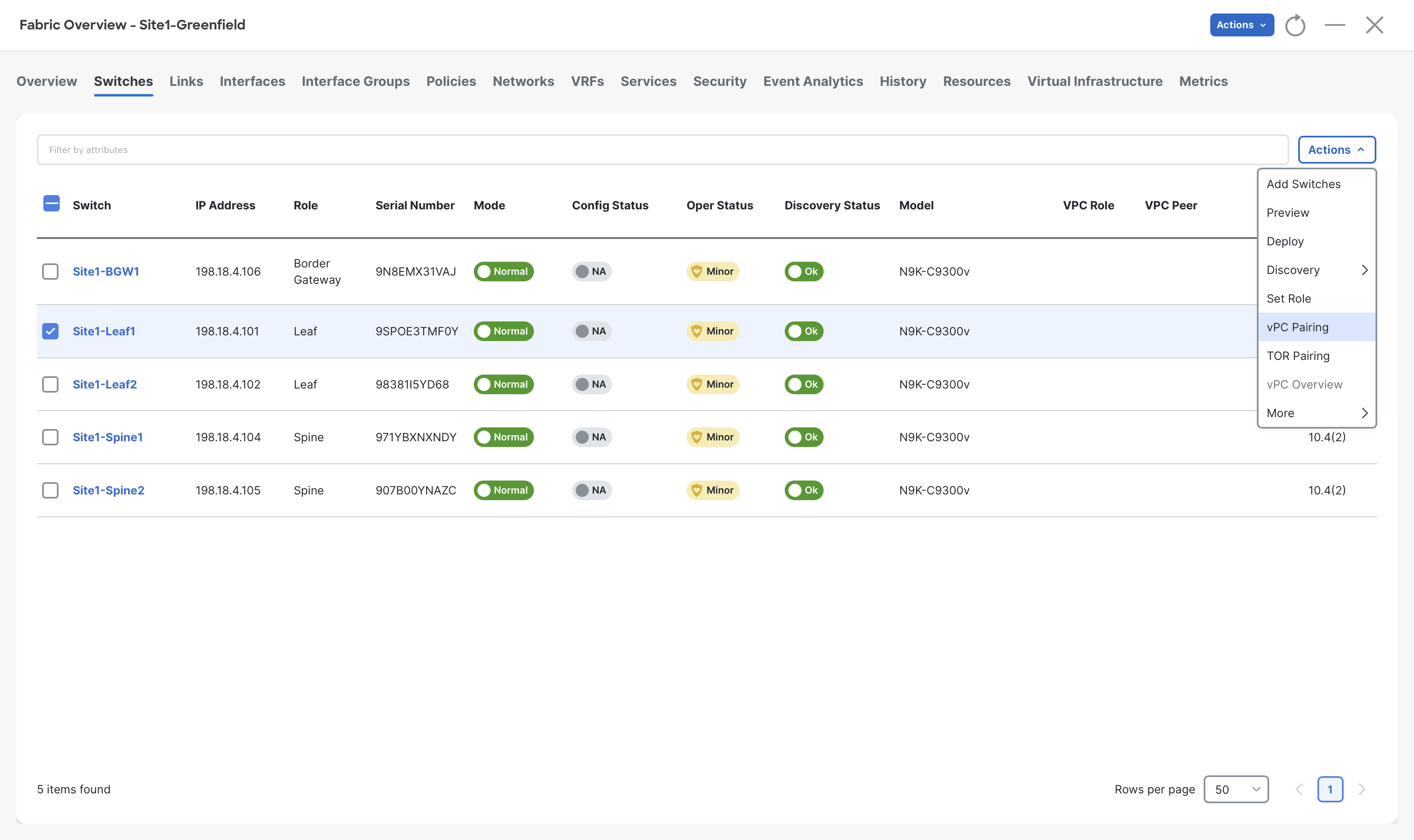
Step 3 - In the vPC Pairing pop-up, select Site1-Leaf2 and click Save at the bottom right
Info
Site1-Leaf2 is recommended by NDFC to form VPC domain with Site1-Leaf1, as it is directly connected and also in same role.
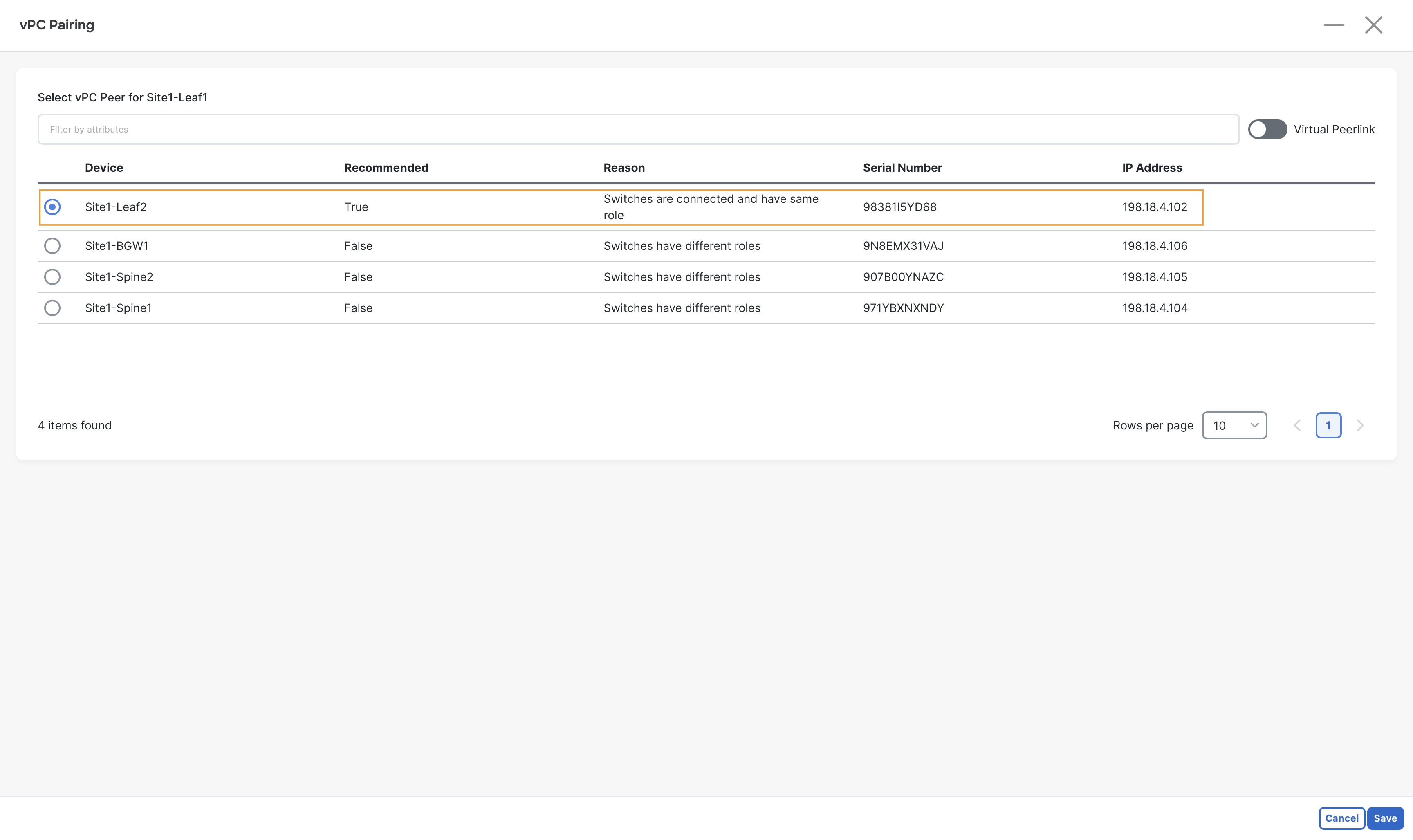
VXLAN EVPN vPC Feature
NDFC also offers vPC fabric peering, which doesn't require a physical peer-link, by providing the knob Virtual Peerlink however, this option is not used in this lab.
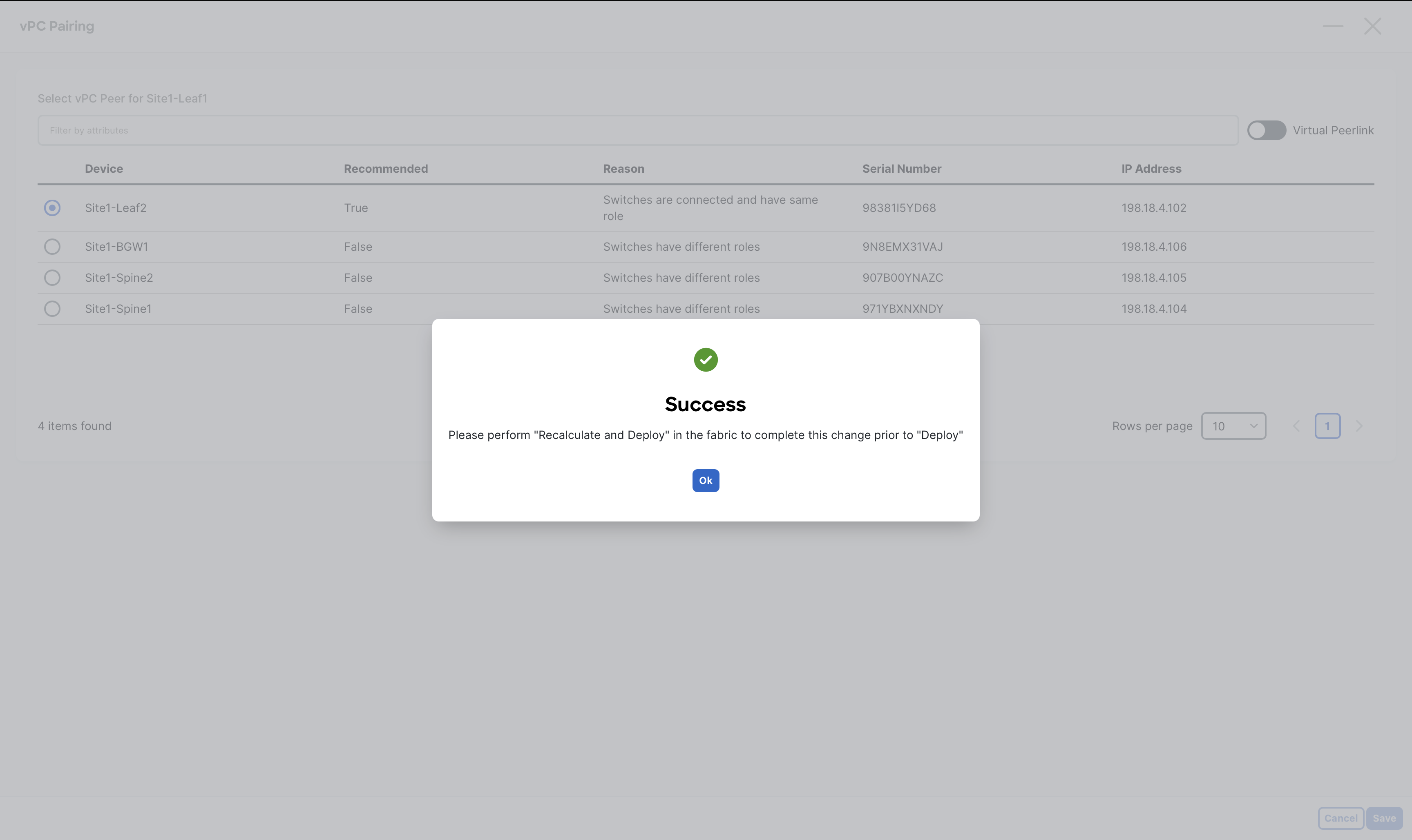
Step 4 - When you receive the warning message about performing a Recalculate Config, click Ok
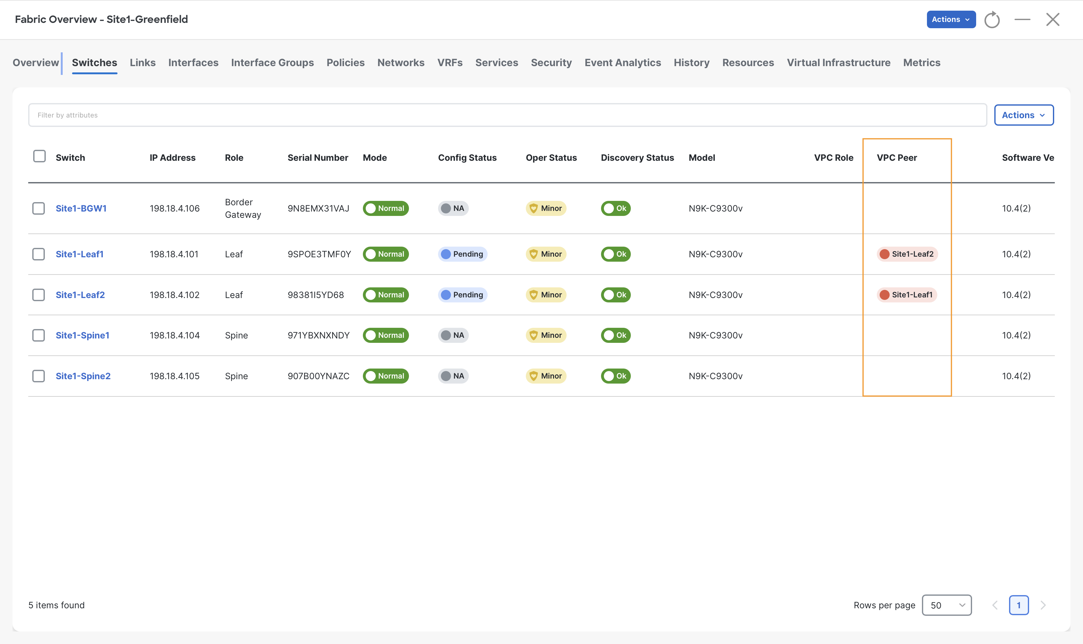
Step 5 - Observe the VPC Peer column indicating the VPC domain formation between Site1-Leaf1 and Site2-Leaf2 switches
Recalculating and Deploying
We have finished defining our intent for the Site1-Greenfield fabric, and are ready to push the respective configuration to the switches via NDFC.
This is a key workflow in NDFC, as the settings we have defined so far have not been added to the switches yet. Only during a Recalculate and Deploy operation NDFC will render all the fabric configurations and deploy on to the switches.
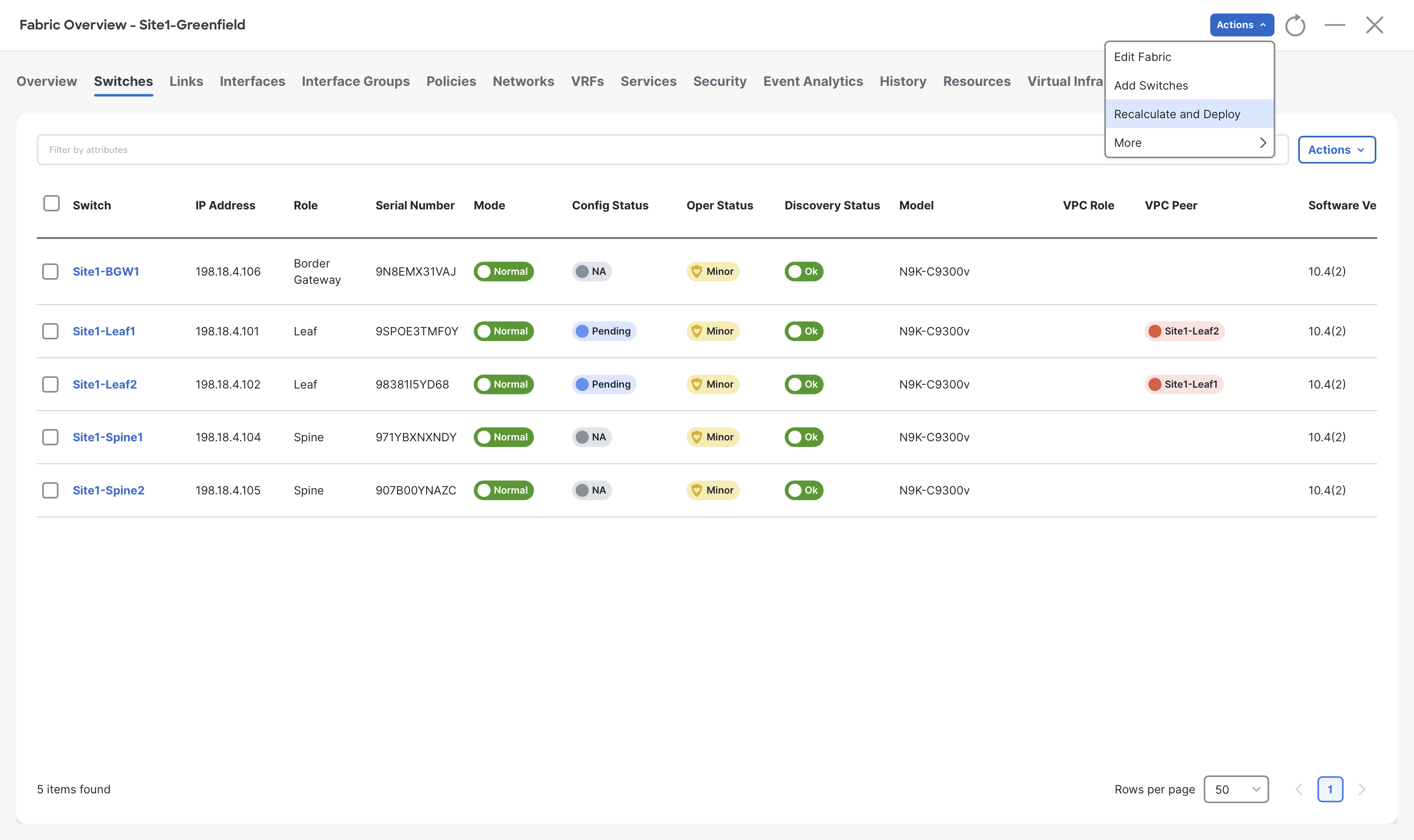
Step 1- On the Fabric Overview page click on Actions > Recalculate and Deploy
Step 2- On the Deploy Configuration page, NDFC shows all the pending configuration for the switches of Site1-Greefield fabric
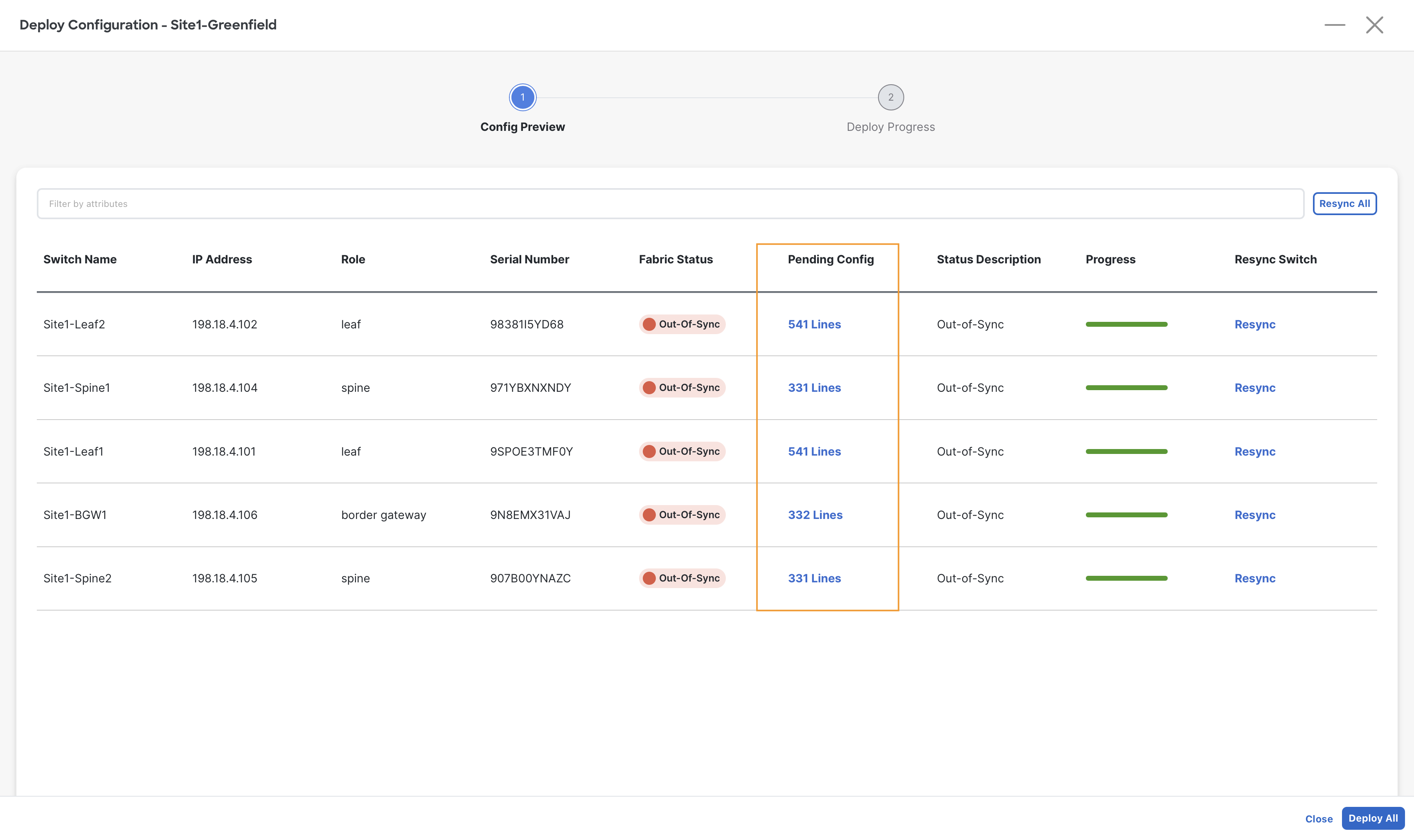
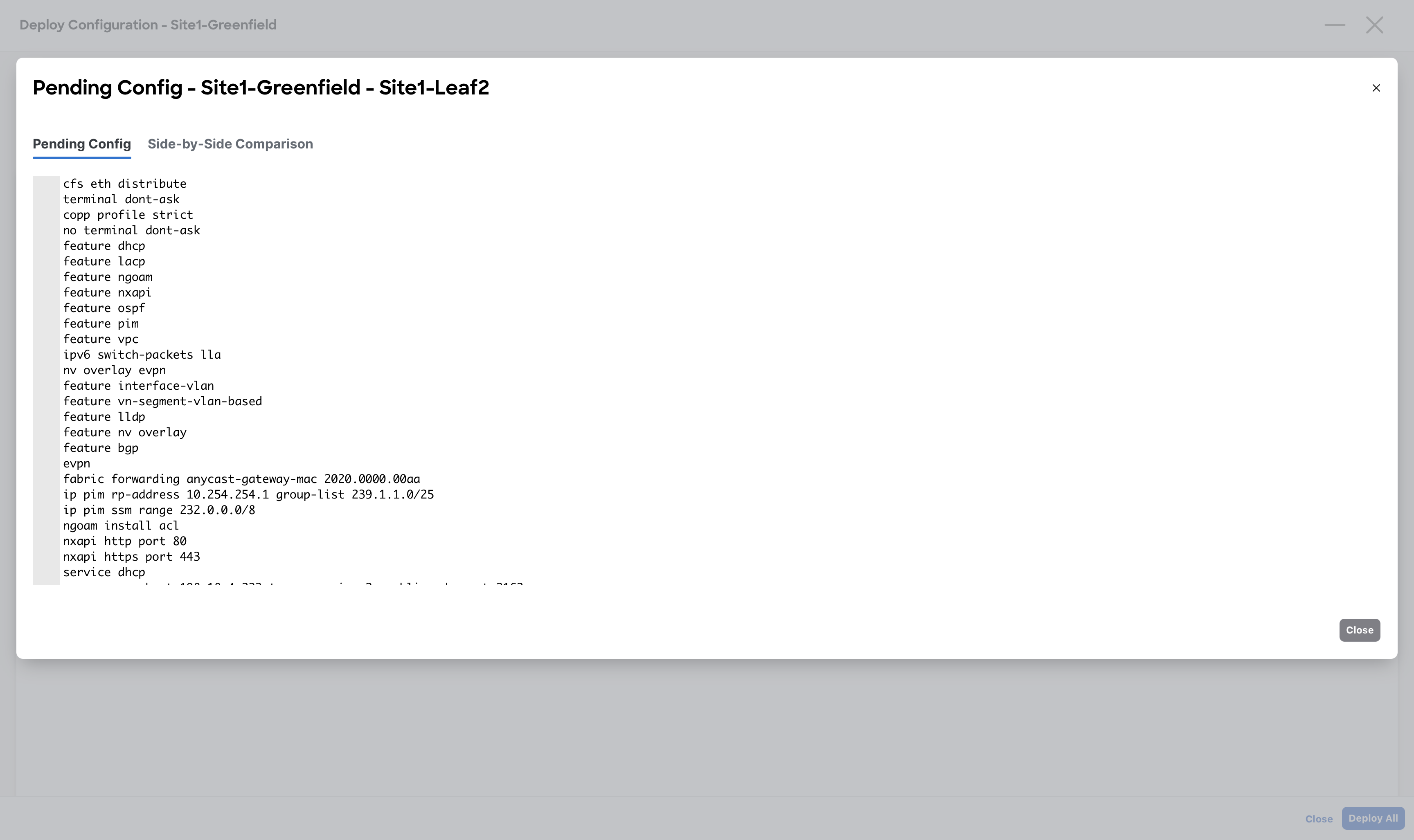
Step 3 – (Optional) On the Deploy Configuration window, click the link in the Pending Config column to preview all the configuration to be pushed by NDFC to the respective switches
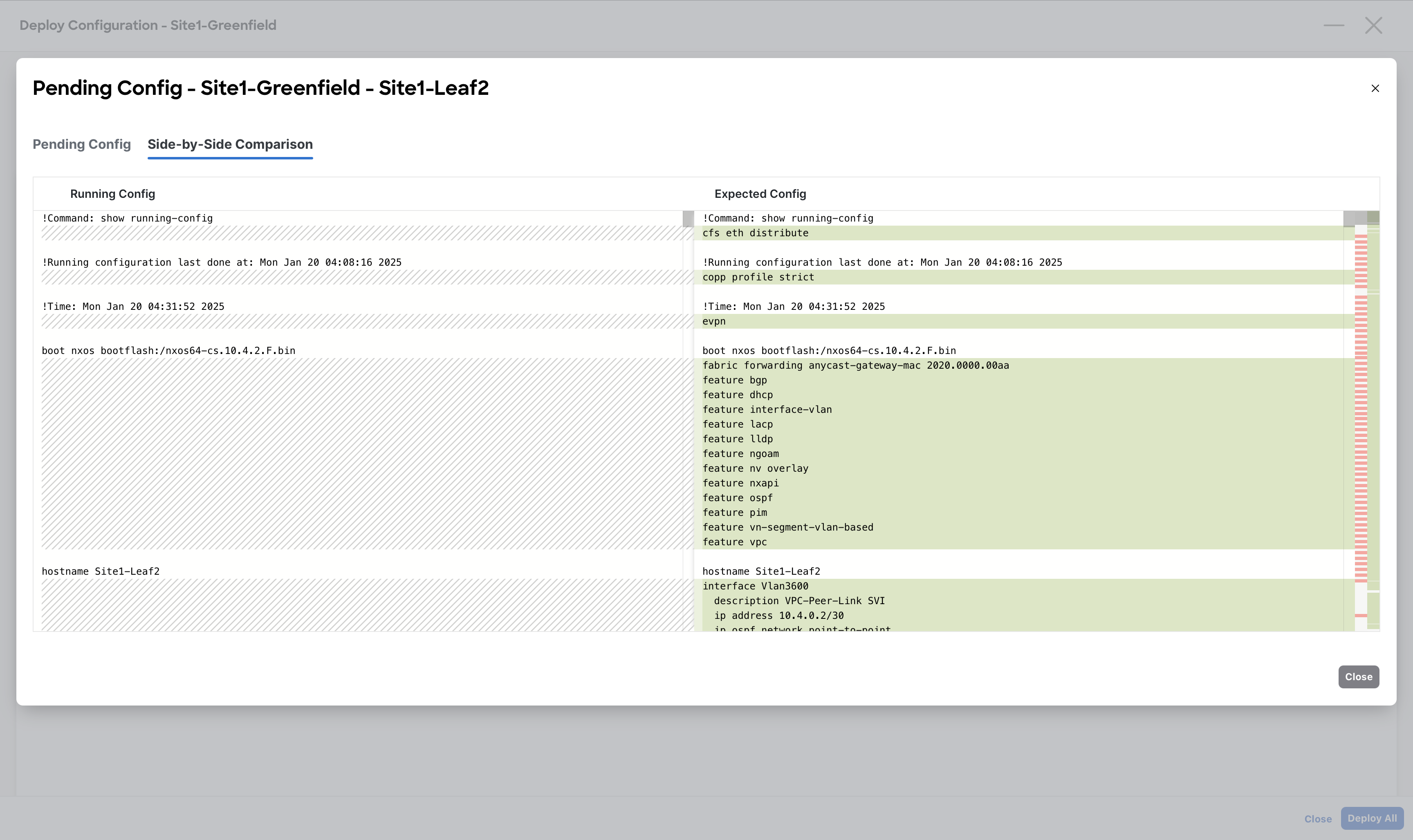
Tip
NDFC also offers a side-by-side comparison between the current and expected configuration. At this stage, it is pretty much useless as we are pushing the entire device configuration. During day-1 operations instead it might be extremely helpful as it will highlight the lines that will be modified.
When done viewing, close the Preview Configuration dialog
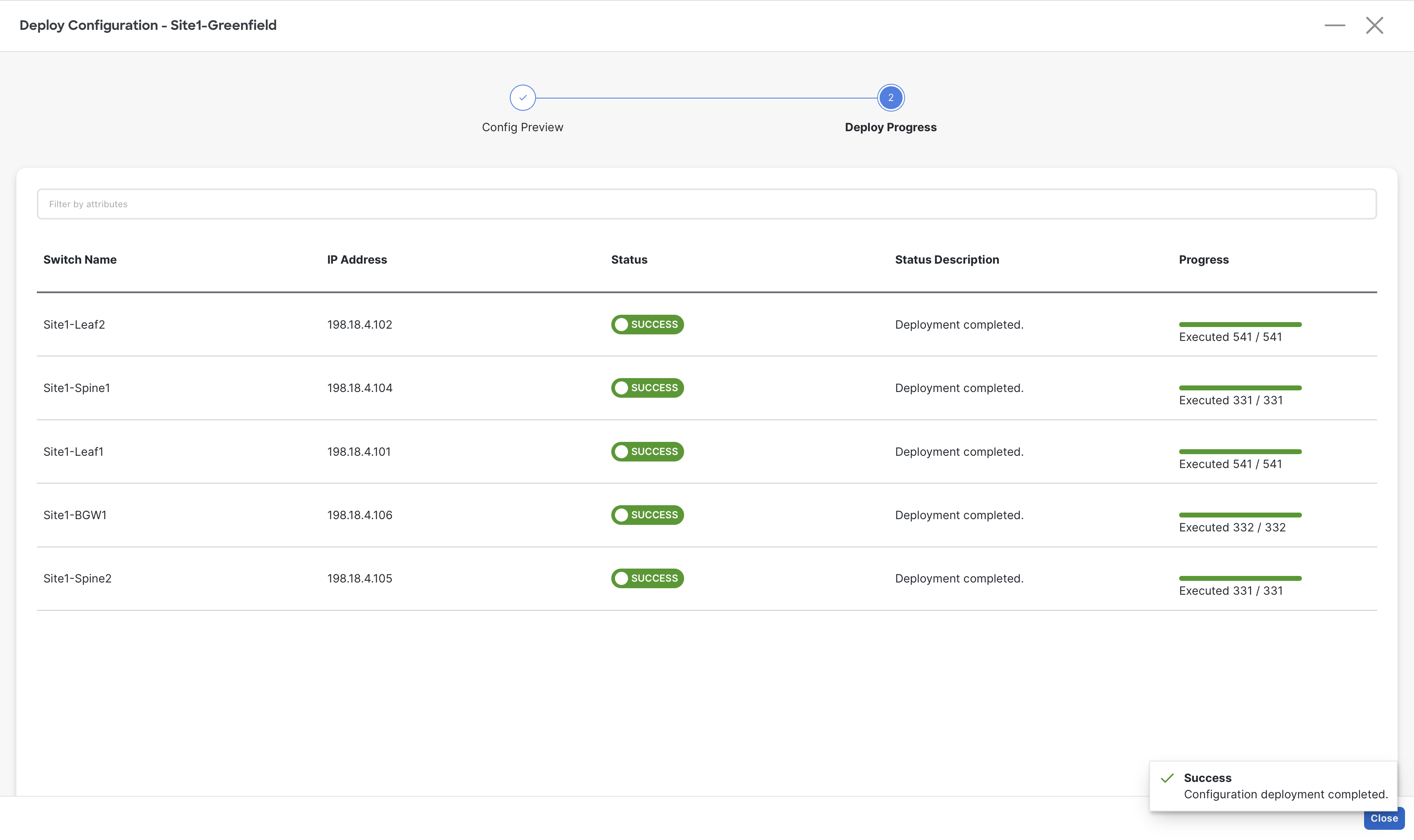
Step 4 – When done reviewing the configuration for all switches, click on Deploy All on the Deploy Configuration page for NDFC to deploy the configuration to the respective switches
Step 5 – Once the deployment is completed for all the switches, click Close to close the Deploy Configuration page
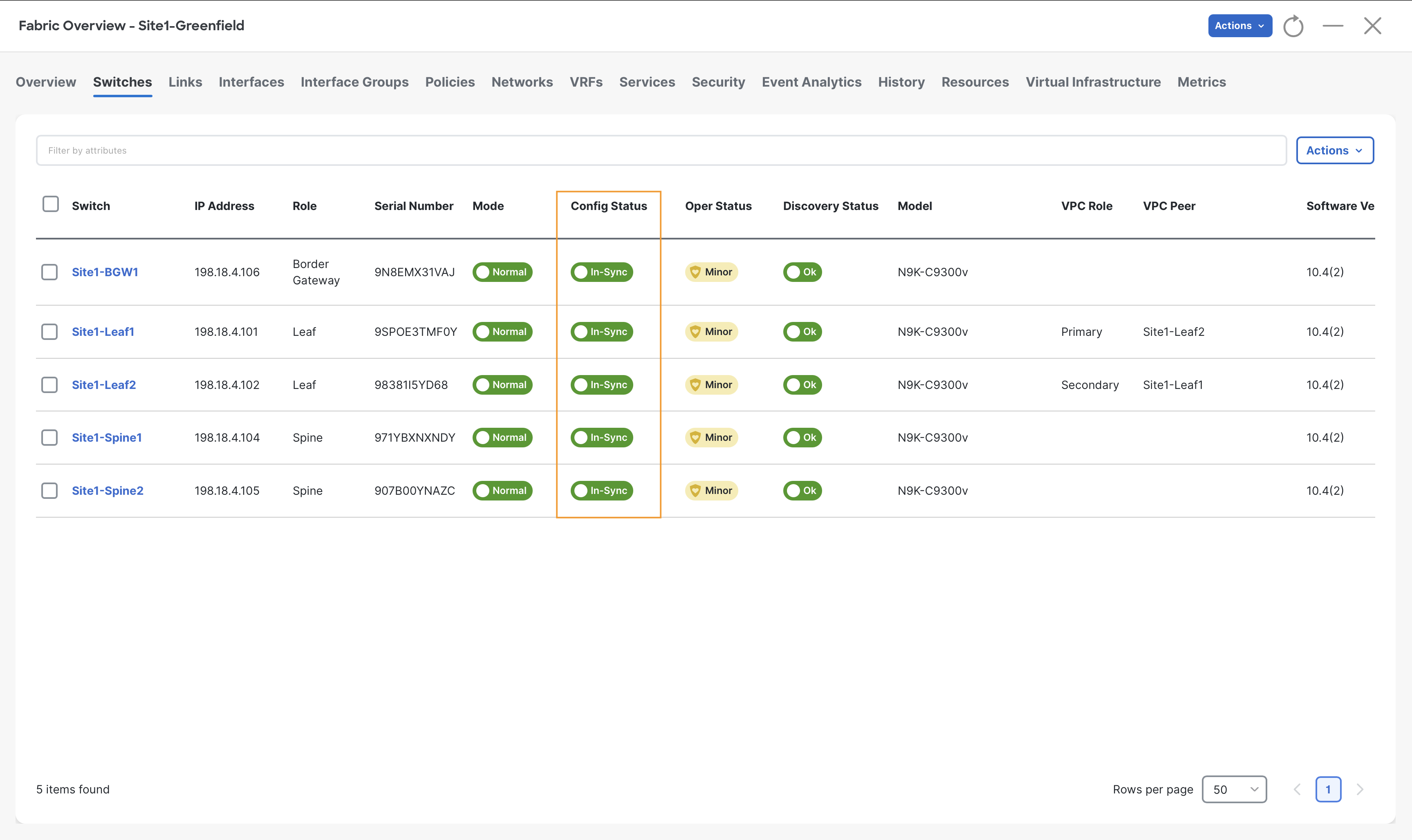
On the Switches tab, notice the Config-Status as In-Sync for all the switches which confirms that all the devices configuration is In-sync with the controller Intent.
Configuring Access Interfaces to Server
Configuring an Orphan Port
Server1 is single attached to Site1-Leaf1 port Eth1/5, which is considered as an Orphan port.
Info
In this lab, we are only using Access ports to connect all servers however, NDFC supports different types of interfaces by offering various interface policy templates.
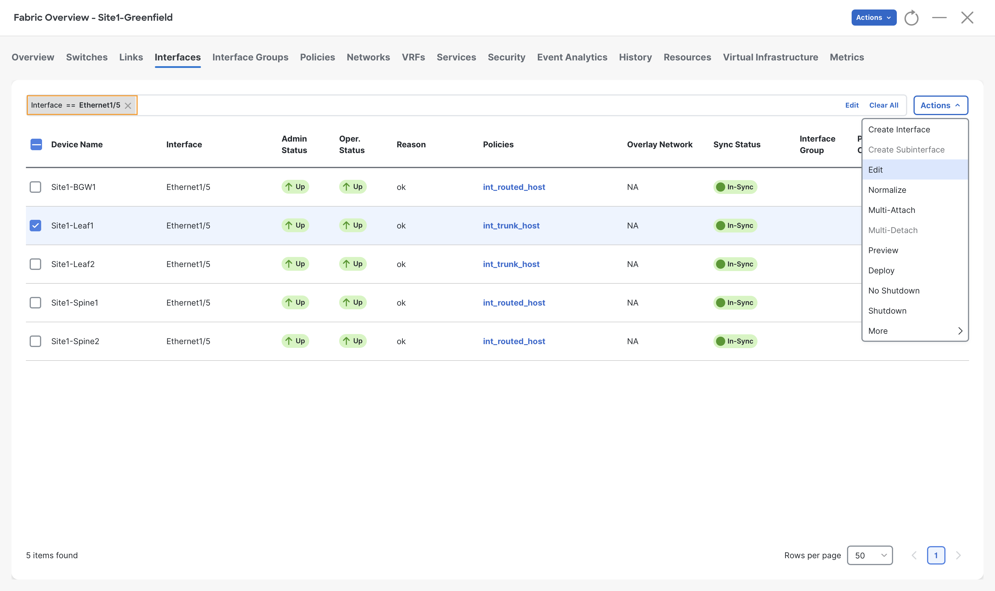
Step 1 - Click on the Interfaces tab for Site1-Greenfield and then enter Interface == Ethernet1/5 in the filter field and hit enter key
Check the box next to Site1-Leaf1 and click Actions > Edit
Info
Notice that Eth1/5 of Site1-Leaf1 is currently configured as a Trunk host as it has the int_trunk_host policy associated. The trunk is the default interface policy for NDFC.
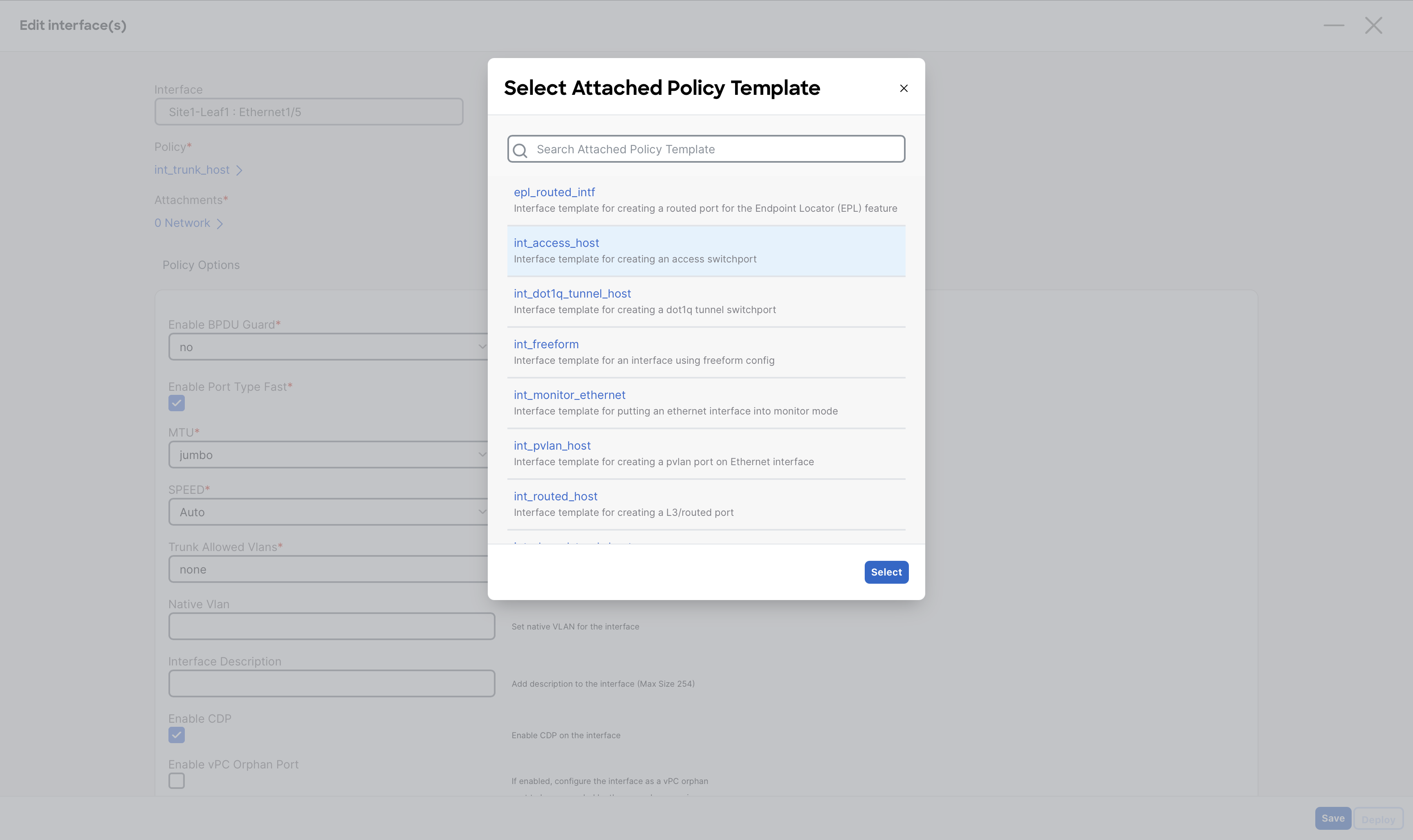
Step 2 – In the Policy list, select the int_access_host policy and click Select
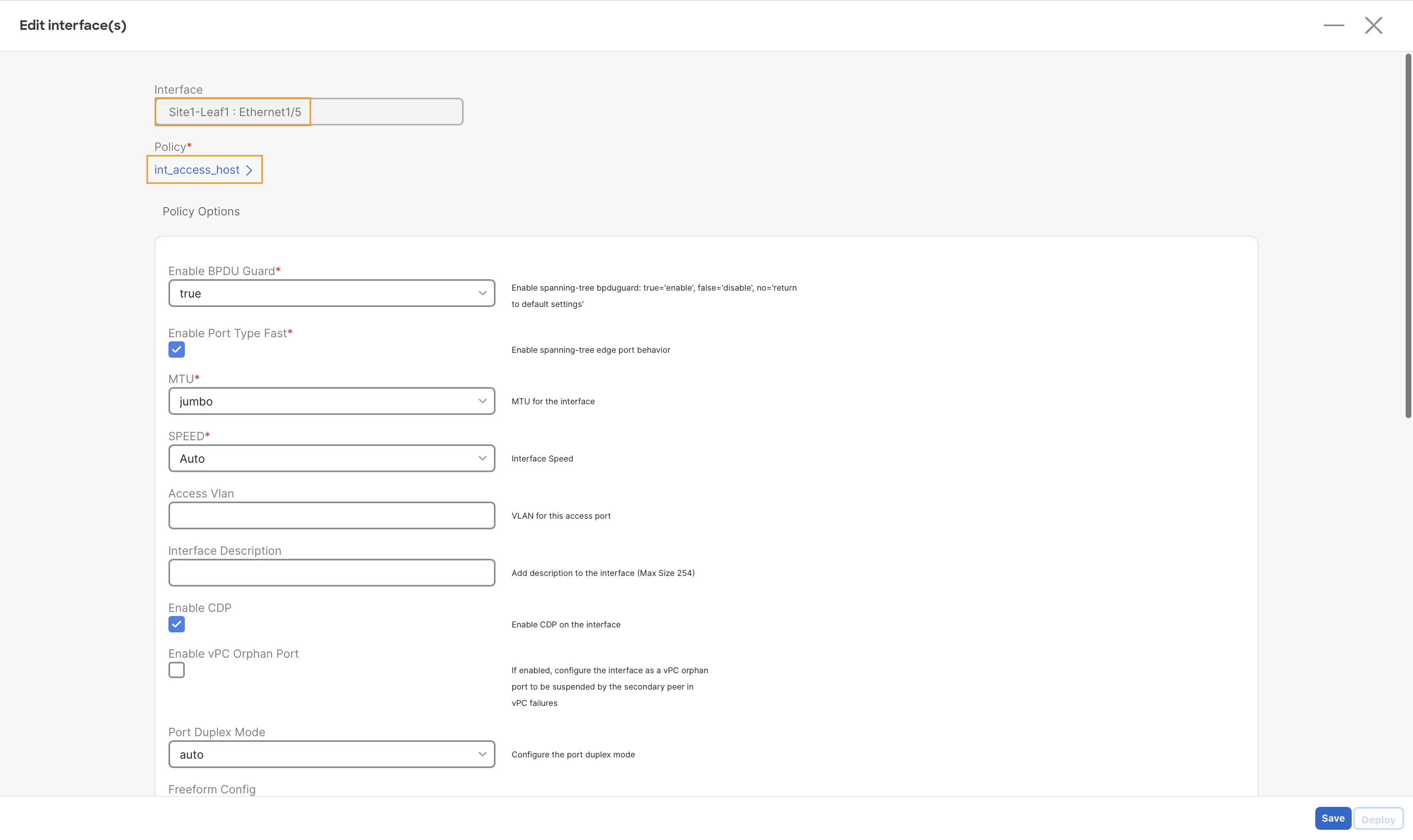
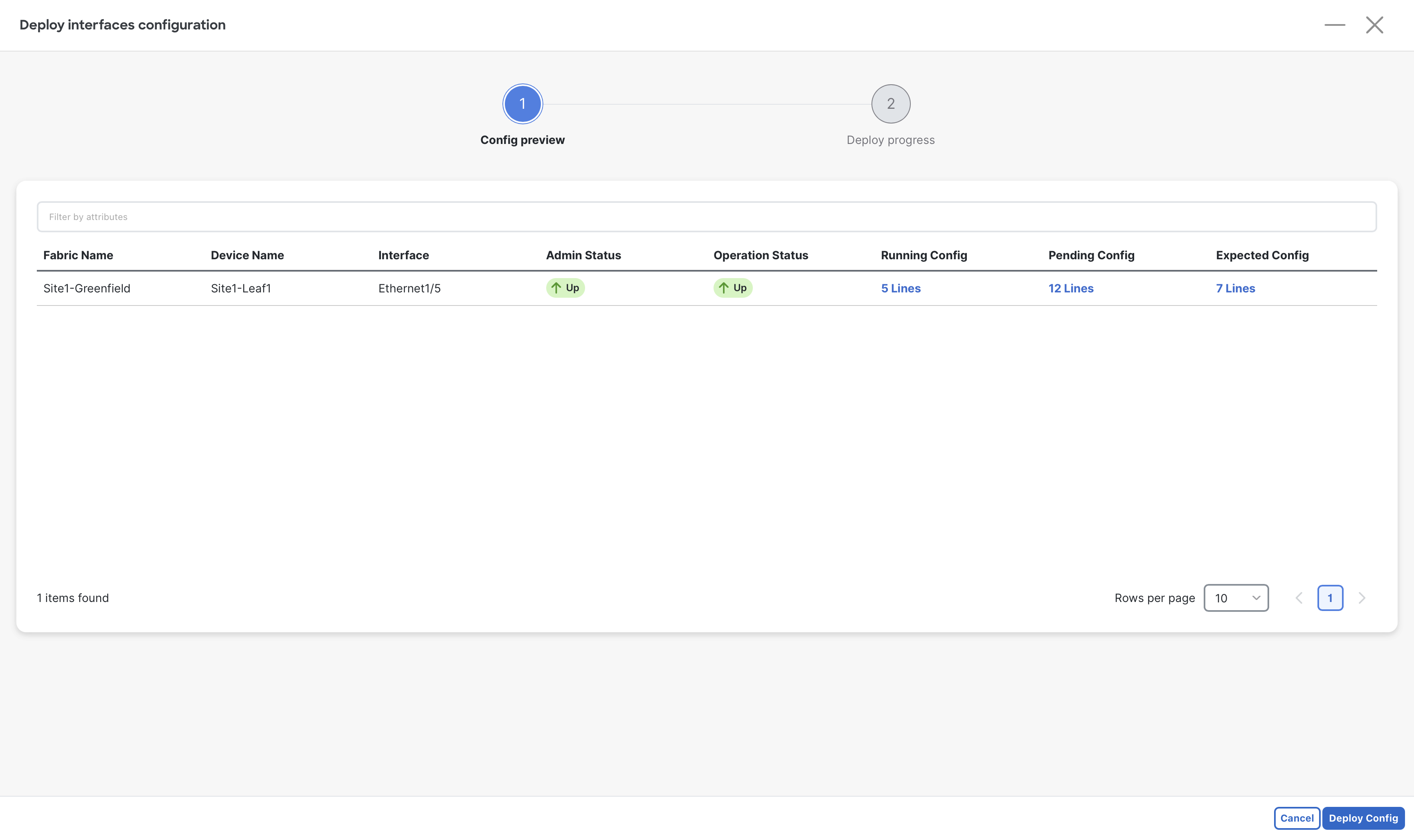
Step 3 – Select Save and then Deploy
Step 4 – (Optional) To view the configuration to be pushed by NDFC, click the lines under Expected Config.
When done viewing, close the Preview Configuration dialog
Step 5 – Click Deploy Config and then close the Edit interface window
Configure vPC Port
Server2 at Site1-Greefield is connected to port Eth1/6 of both Site1-Leaf1 & Site1-Leaf2 switches and is configured with LAG (Link Aggregation) for Active/Active Dual-homing. Since we have formed a vPC domain using Site1-Leaf1 & Site1-Leaf2, we can create a downstream vPC towards Server2.
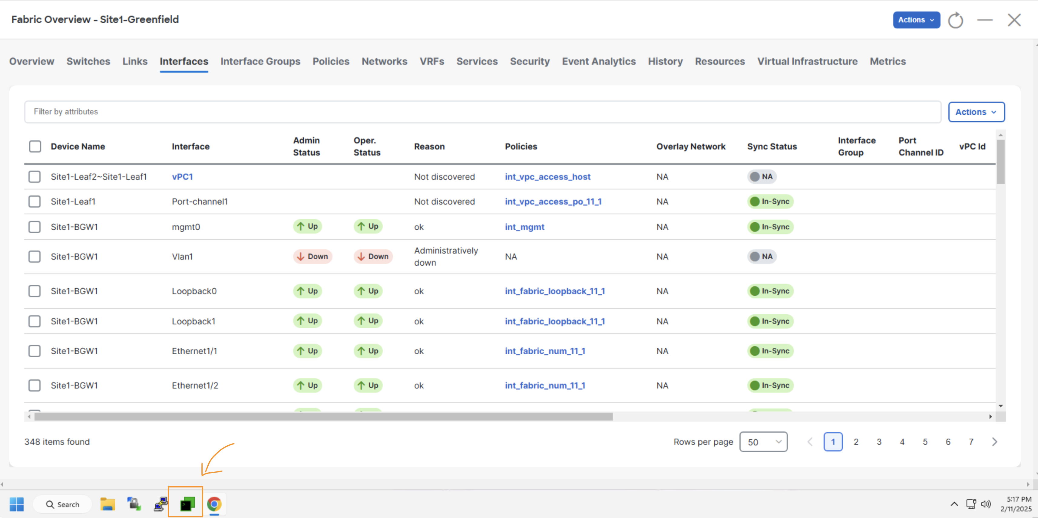
Step 1 – Navigate to the Manage > Fabrics page and double-click on the Site1-Greenfield Fabric.
Step 2 – Proceed to the Interfaces tab of Site1-Greenfield.
Step 3 - On the Interfaces tab, click Actions > Create Interface
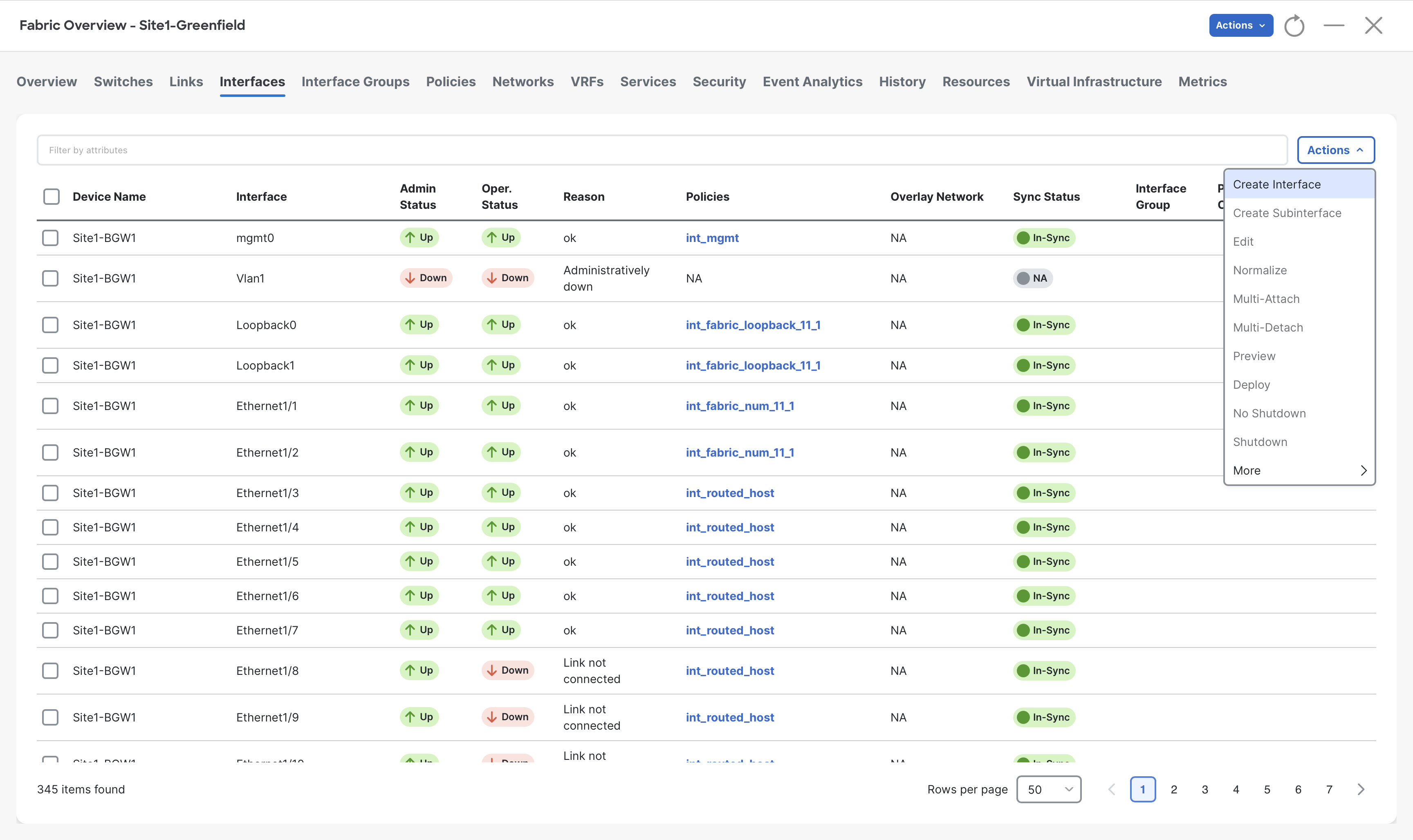
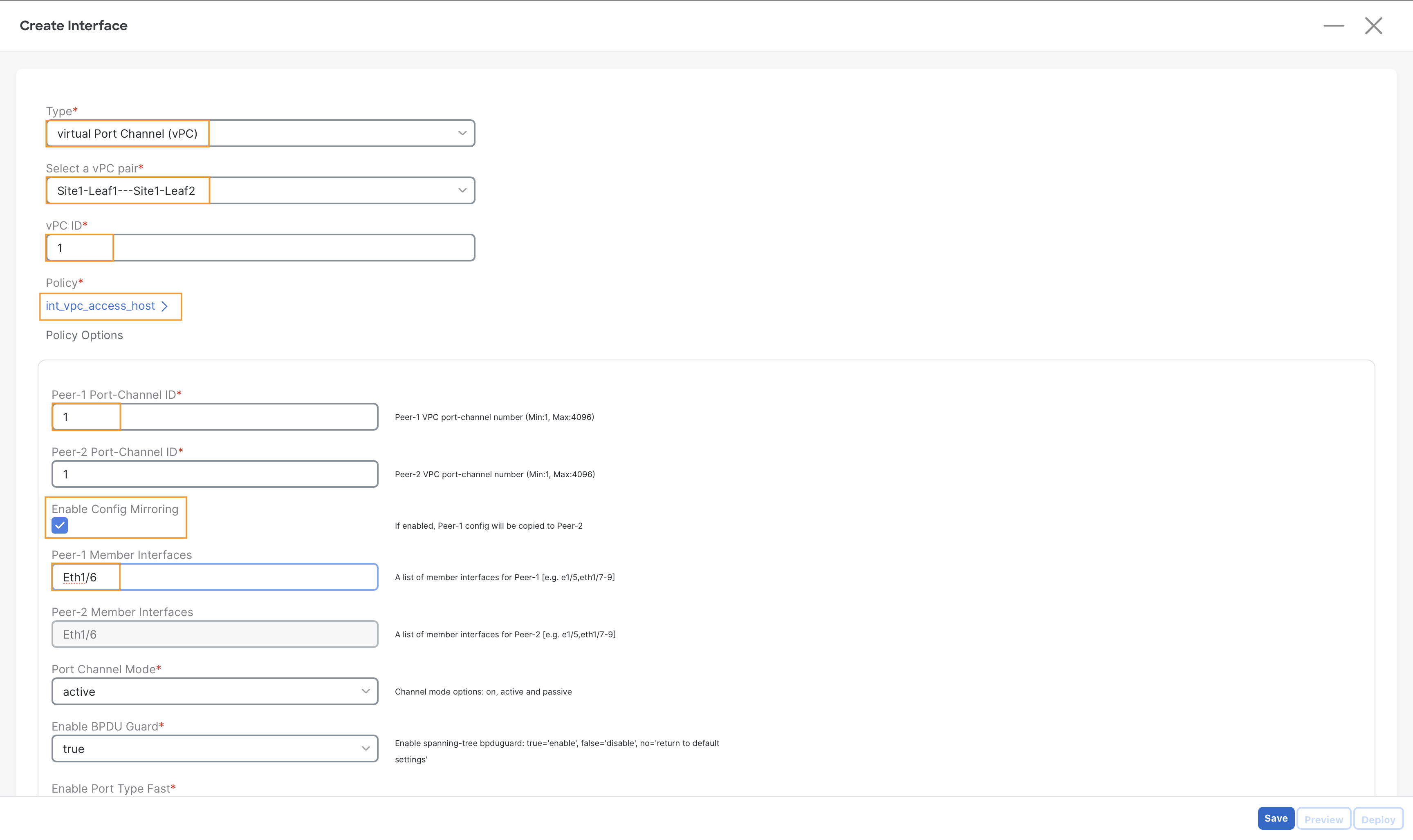
Step 4 – On the Create Interface page, input the following parameters to create a vPC towards Server2–
- Type – virtual Port-Channel (vPC)
- Select vPC Pair – Site1-Leaf1==Site1-Leaf2
- vPC ID - 1
- Policy – int_vpc_access_host
- Enable Config Mirroring Check box
- Peer-1 Member Interfaces – Eth1/6
Warning
Ensure you are selecting the right policy int_vpc_access_host. Leaving the default one will prevent the traffic forwarding for this server by the switches.
Step 5 – Click on Save, then select Deploy.
Step 6 – (Optional) In the Deploy Configuration window, click the link in the Pending Config column to preview the configuration.
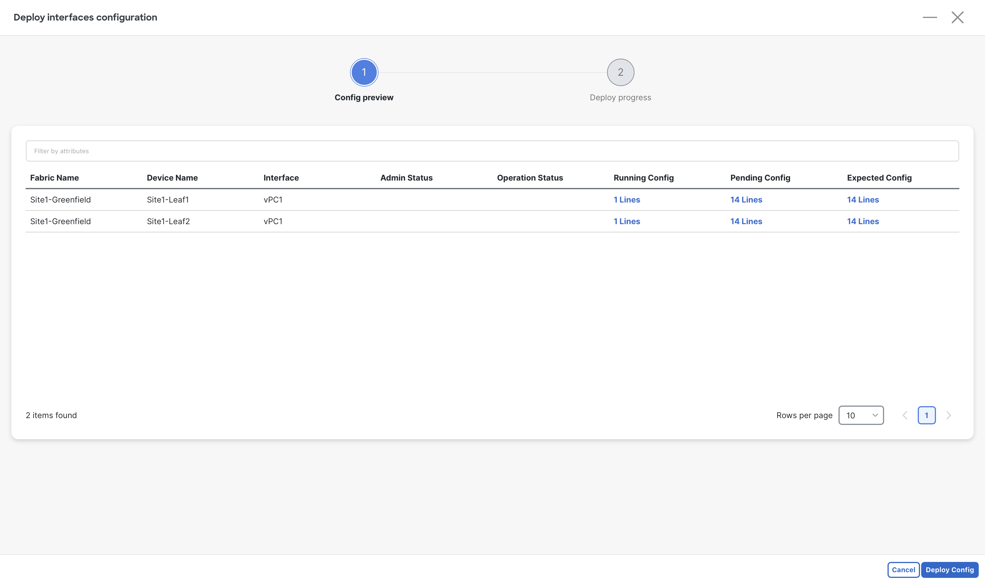
Step 7 – Click Deploy All to push the configuration to switches.
Step 8 – Close the Create Interface page.
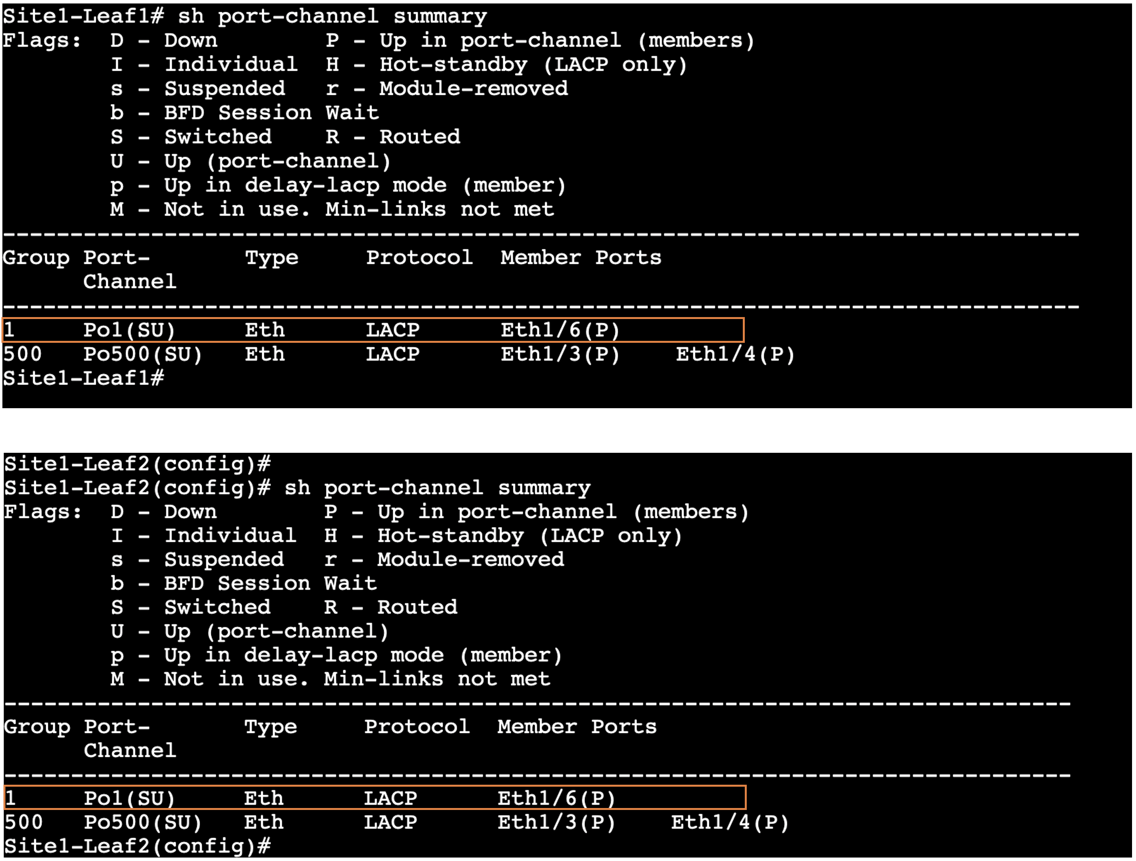
Step 9 – (Optional) Validate the vPC status
-
Open MPutty:
- Locate MPutty either on your desktop or from the Windows start bar.
- Locate MPutty either on your desktop or from the Windows start bar.
-
Access the Switches:
- Once MPutty is opened, expand the menu labeled Site1-Greenfield Fabric.
- Double-click on Site1-Leaf1 to access the first switch.
- Repeat the process by double-clicking on Site1-Leaf2 to access the second switch.
-
Run the Command:
- On both switches, execute the command:
show port-channel summary. - This command will display the vPC status, which you need to validate.
- On both switches, execute the command:
Site1-Leaf1
show port-channel summary
Site1-Leaf2
show port-channel summary
Verify Site1-Greenfield Fabric
A quick verification at this point can be done by looking at the MP-BGP EVPN sessions between spines and leafs. You will find the BGP EVPN sessions are up which mean the follwoings:
- Point-to-Point interfaces between Spines and Leafs have been configured correctly
- IGP Routing protocol in Underlay is correctly advertising the loopback addresses of the devices
- BGP EVPN sessions have been configured properly
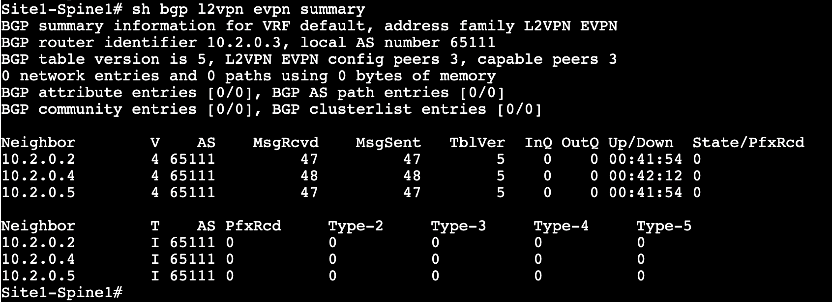
Step 1 - On MPutty, expand Site1-Greenfield Fabric and login to Site1-Spine1 & Site1-Spine2 switches. Then, run the following commands
Site1-Spine1
show bgp l2vpn evpn summary
Site1-Spine2
show bgp l2vpn evpn summary
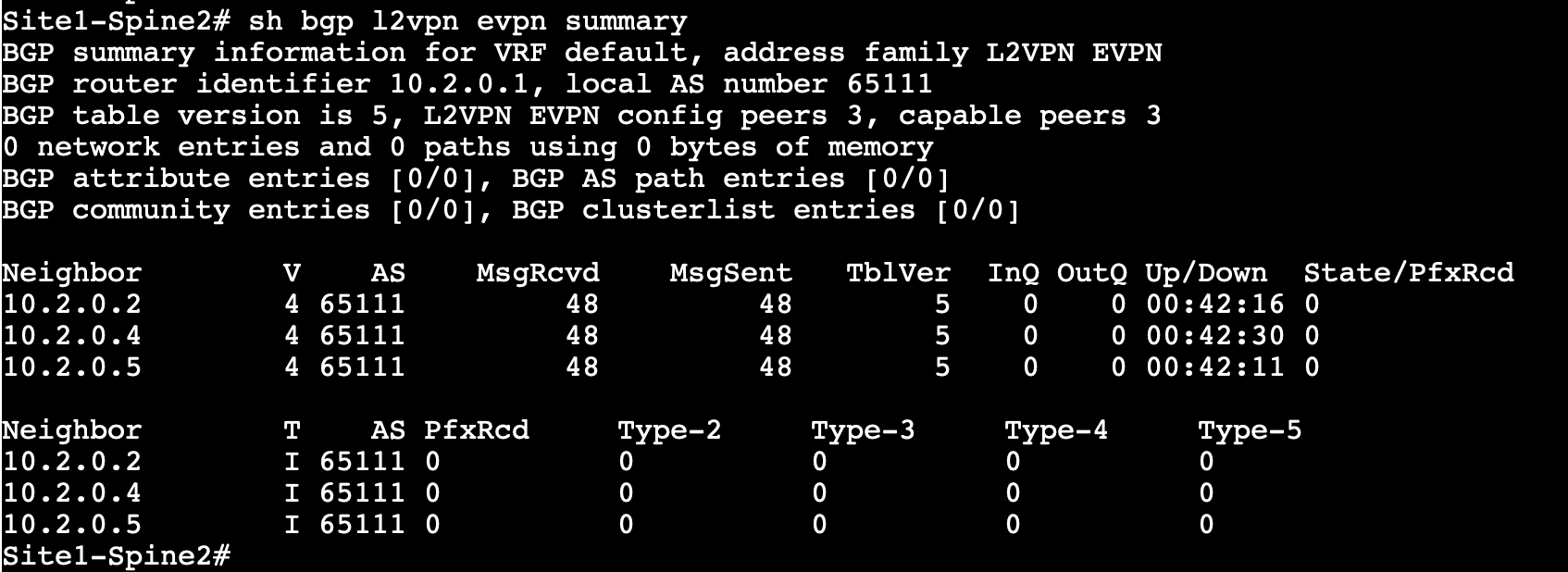
Observe the output. Both Spines should have three neighbors (Site1-Leaf1, Site1-Leaf2, Site1-BGW) for the L2VPN EVPN address family.
Note
You might see different Neighbor IDs in the output as these IPs are dynamically assingned by NDFC.
Info
At this moment, no EVPN routes are learned as no VRFs/Networks have been created yet.
Step 2 – From the Fabric Controller page, click Overview and go to Topology tab
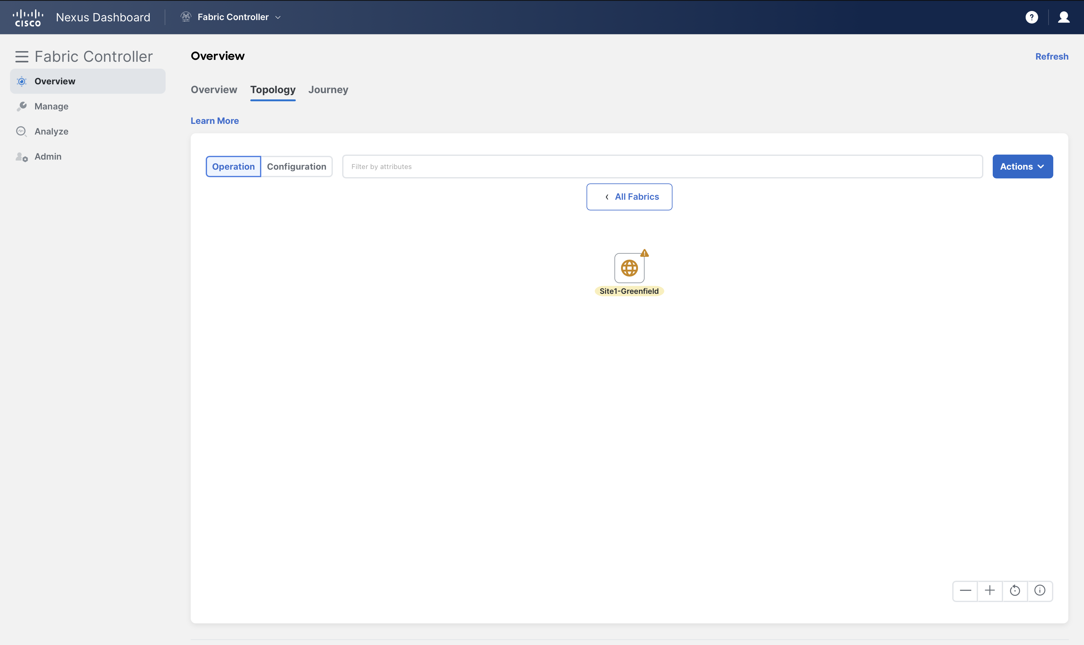
double-click on Site1-Greenfield and change to Configuration view to view real-time topology
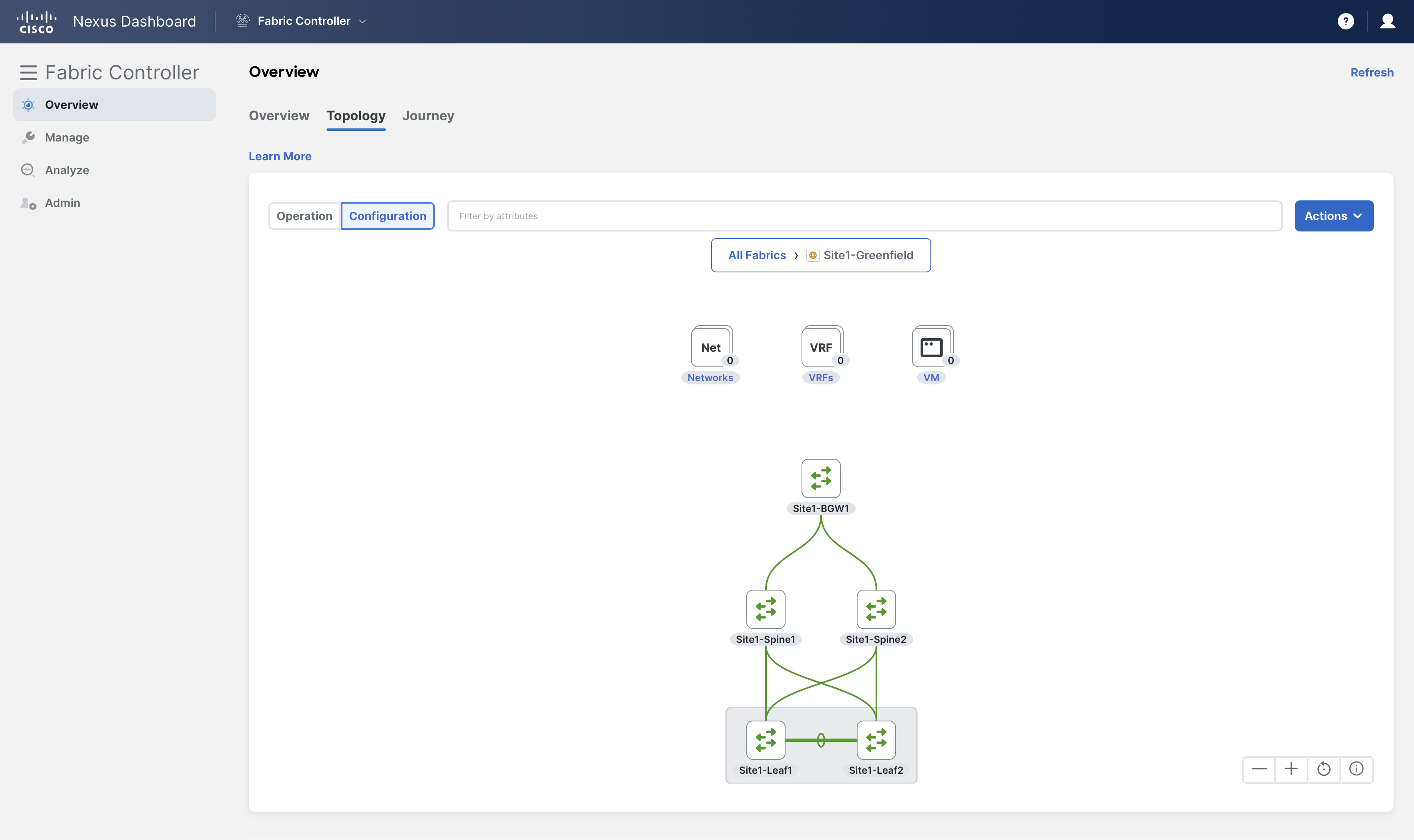
Info
NDFC displays a real-time topology for the fabrics and uses different legends for switches/fabrics based on their health/configuration status.
Also, note that there are no networks or VRFs created for this fabric yet.
You can continue now with Task #2