Task 2 - Import Brownfield Fabric into NDFC
Overview
NDFC's VXLAN EVPN Fabric Brownfield Import is a robust feature designed to integrate an existing VXLAN EVPN fabric (reffered as brownfield ) for streamlined management via NDFC. This functionality allows for the preservation of existing configurations and operational states during the integration process.
The primary advantage of this feature is the seamless transition from cli-based individual switch management to NDFC based centralized fabric management system without causing disruptions to current network operations. It also leverages the capabilities of NDFC to provide enhanced visibility, simplified administration, and automated operations for VXLAN EVPN fabrics, thus increasing efficiency and reducing potential errors.
Review Existing Brownfield Configuration
Step 1 - Double-click the MPuTTY desktop shortcut.
Step 2 - Expand Site2-Brownfield Fabric, then double-click on Site2-Leaf1.
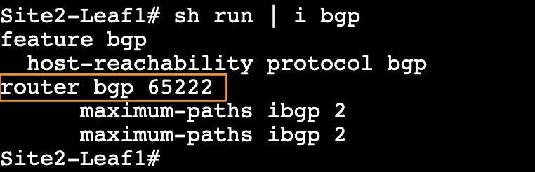
Step 3 - Enter the command show run | i bgp and note down the BGP ASN used for Site2.
Site2-Leaf1
show run | i bgp
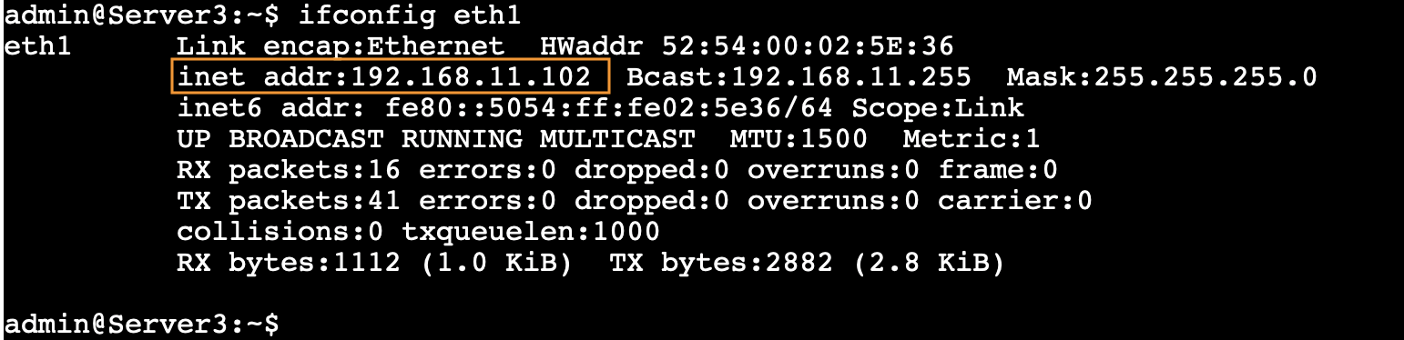
Step 4 - Log in to Server3 at Site2-Brownfield and note down the IP Address configured using the command ifconfig eth1.
- IP Address - 192.168.11.102/24
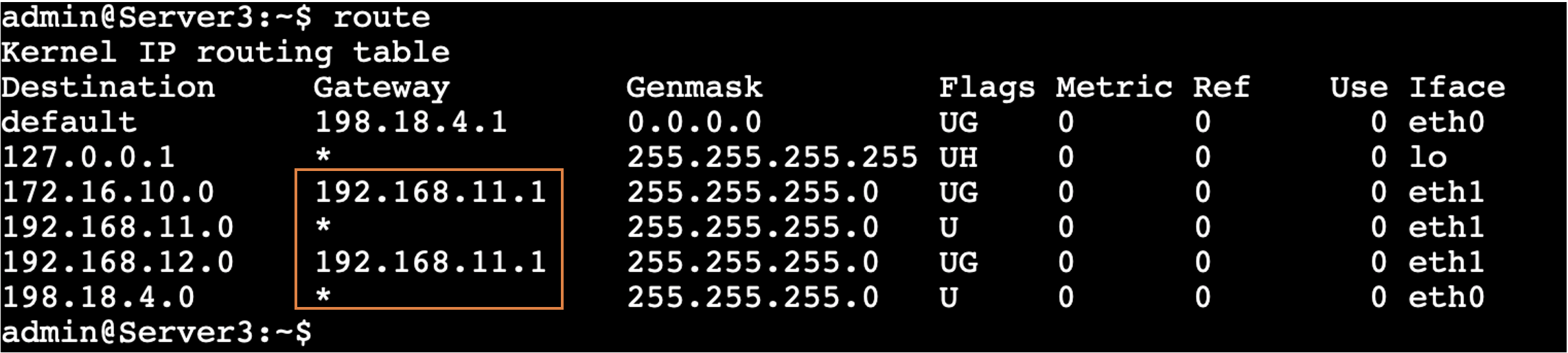
- IP Gateway – 192.168.11.1
Server3
ifconfig eth1
To check the Gateway, enter the route command.
Server3
route
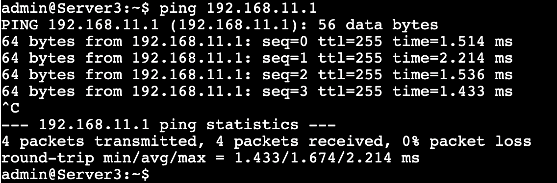
Step 5 – Verify the ping test to the Gateway IP 192.168.11.1 from Server3
Server3
ping 192.168.11.1
Step 6 – (Optional) Log in to Site2-Leaf1 and perform the following validation.
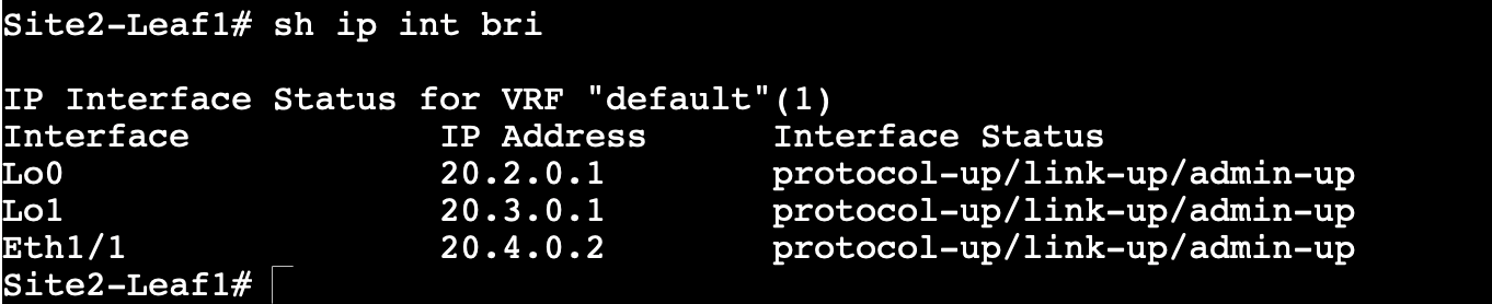
a) Run the command show ip interface brief and observe the IP addresses configured on Loopback and Ethernet interfaces.
Site2-Leaf1
show ip int brief
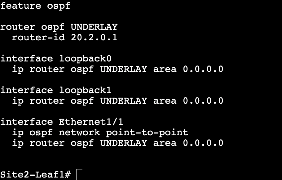
b) Observe the underlay routing protocol running on the device.
Site2-Leaf1
show run ospf
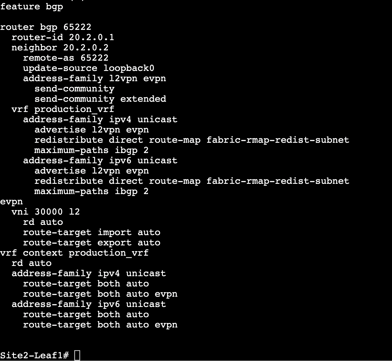
c) Verify the BGP configuration.
Site2-Leaf1
show run bgp
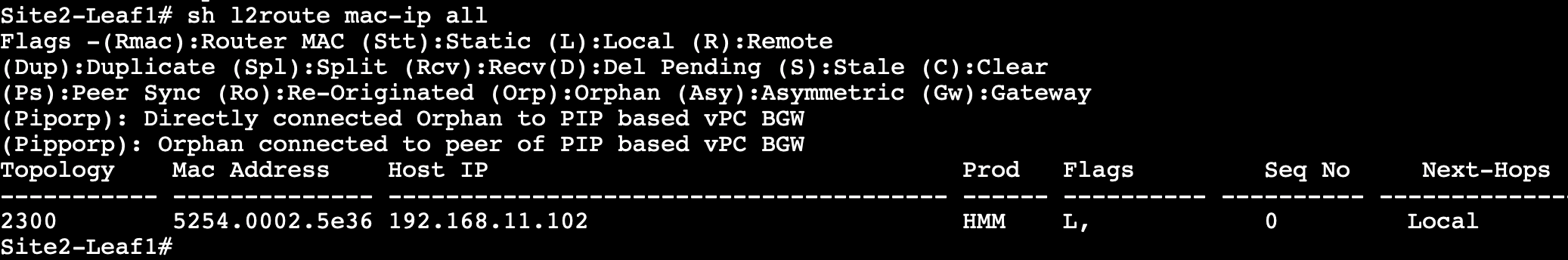
d) Run the command show l2route mac-ip all and observe Server3’s MAC and IP addresses learned on Site2-Leaf1.
Note
The MAC address you'll see will be different as each lab is using a different set of VMs.
Site2-Leaf1
show l2route mac-ip all
e) Run the command show bgp l2vpn evpn 192.168.11.102 and observe the EVPN Type-2 route generated by Site2-Leaf1 for Server3's IP addresses.
Site2-Leaf1
show bgp l2vpn evpn 192.168.11.102
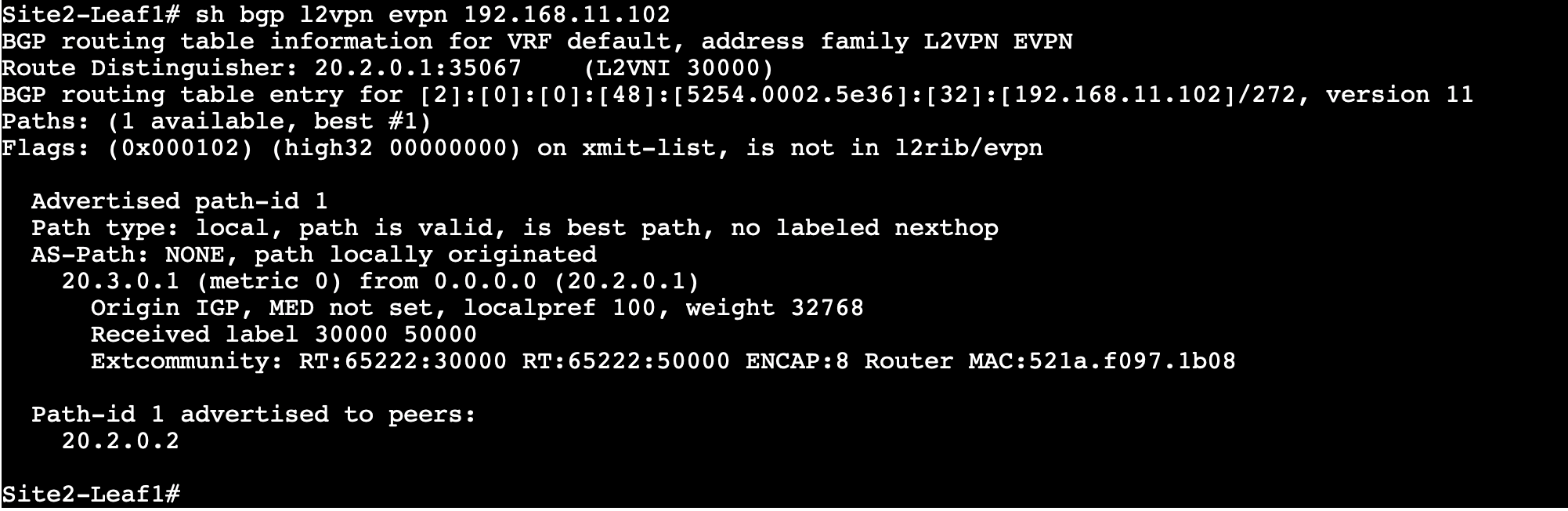
Info
All of these verification tasks have been designed to demonstrate that Site-2 is a fully functional fabric with all the control and data plane functions fully operational.
Create Brownfield VXLAN EVPN Fabric in NDFC
Step 1 – (If NDFC not already opened) Double-click the Chrome desktop shortcut and sign in to Nexus Dashborad with following credentials
Username = admin
Password = C1sco12345
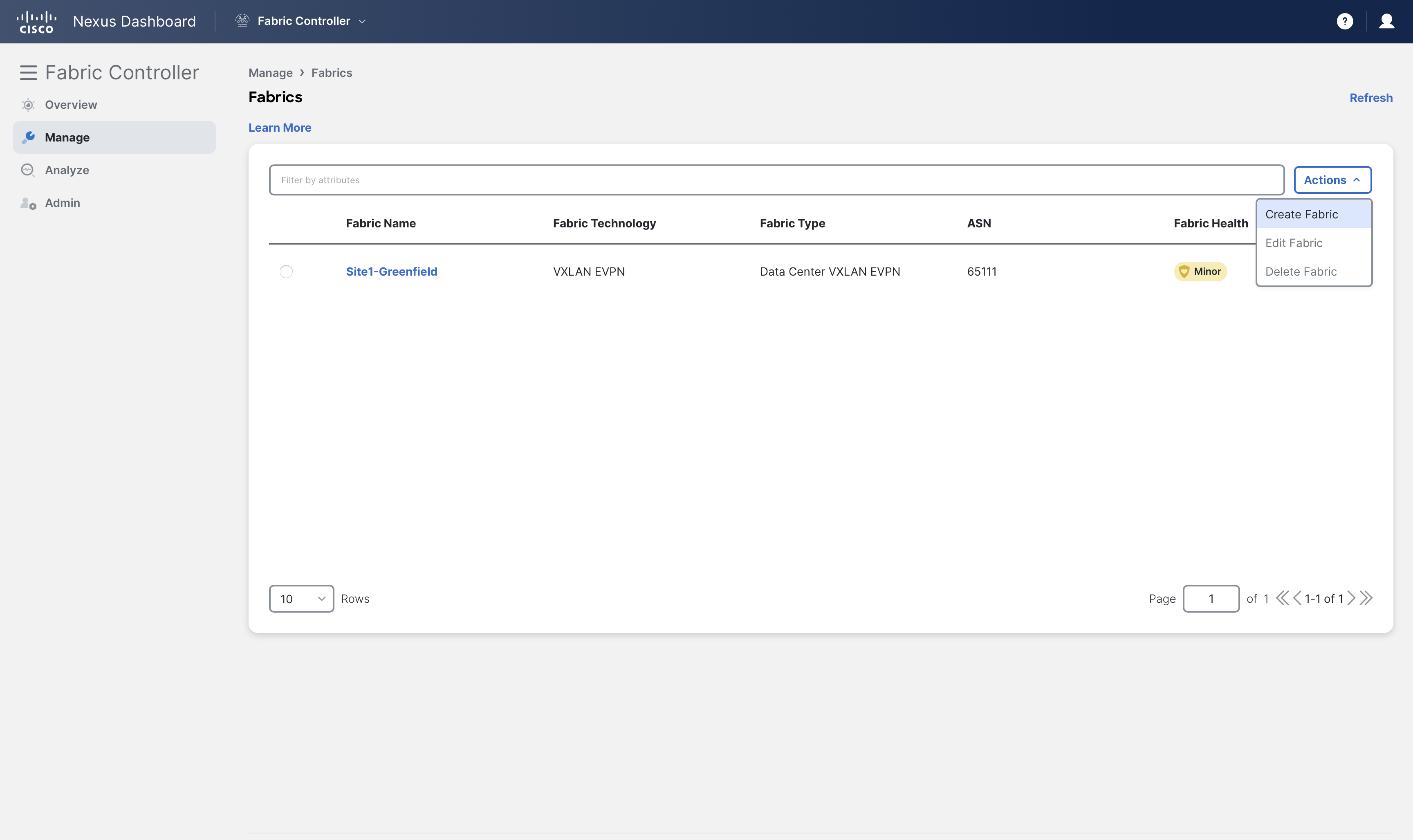
Step 2 - On Fabric Controller page, click Manage > Fabrics and then click on Create Fabric from Actions drop-down
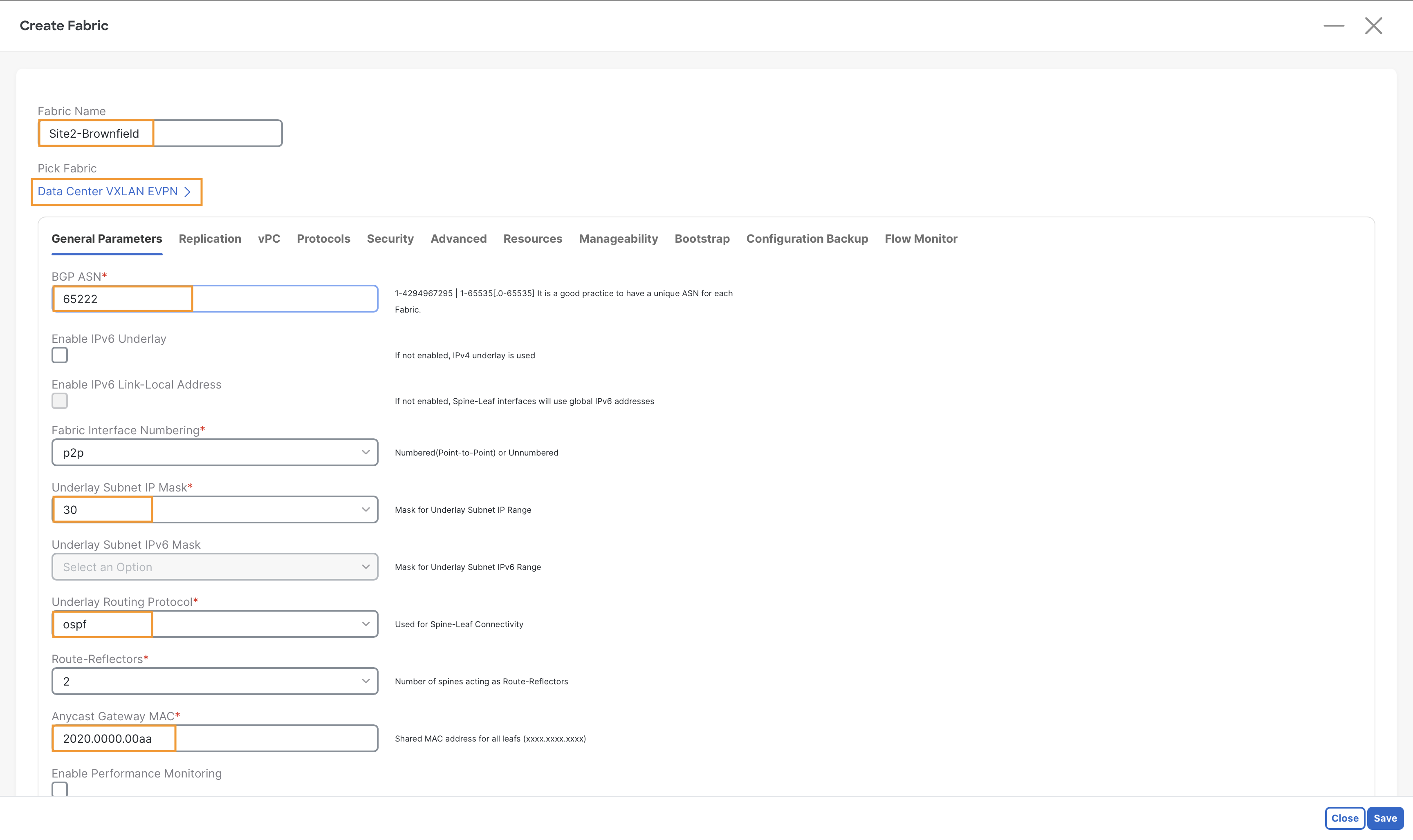
Step 3 – In the Fabric Name field, enter Site2-Brownfield. Then, click Choose Fabric, choose Data Center VXLAN EVPN fabric template, and click Select.
Step 4 – Under the General Parameters tab, in the BGP ASN field, enter 65222.
Also validate the following parameters to match the configuration of Site2-Leaf1:
- Underlay Subnet IP Mask - 30.
- Underlay Routing protocol - OSPF.
- Anycast Gateway MAC - 2020.0000.00aa.
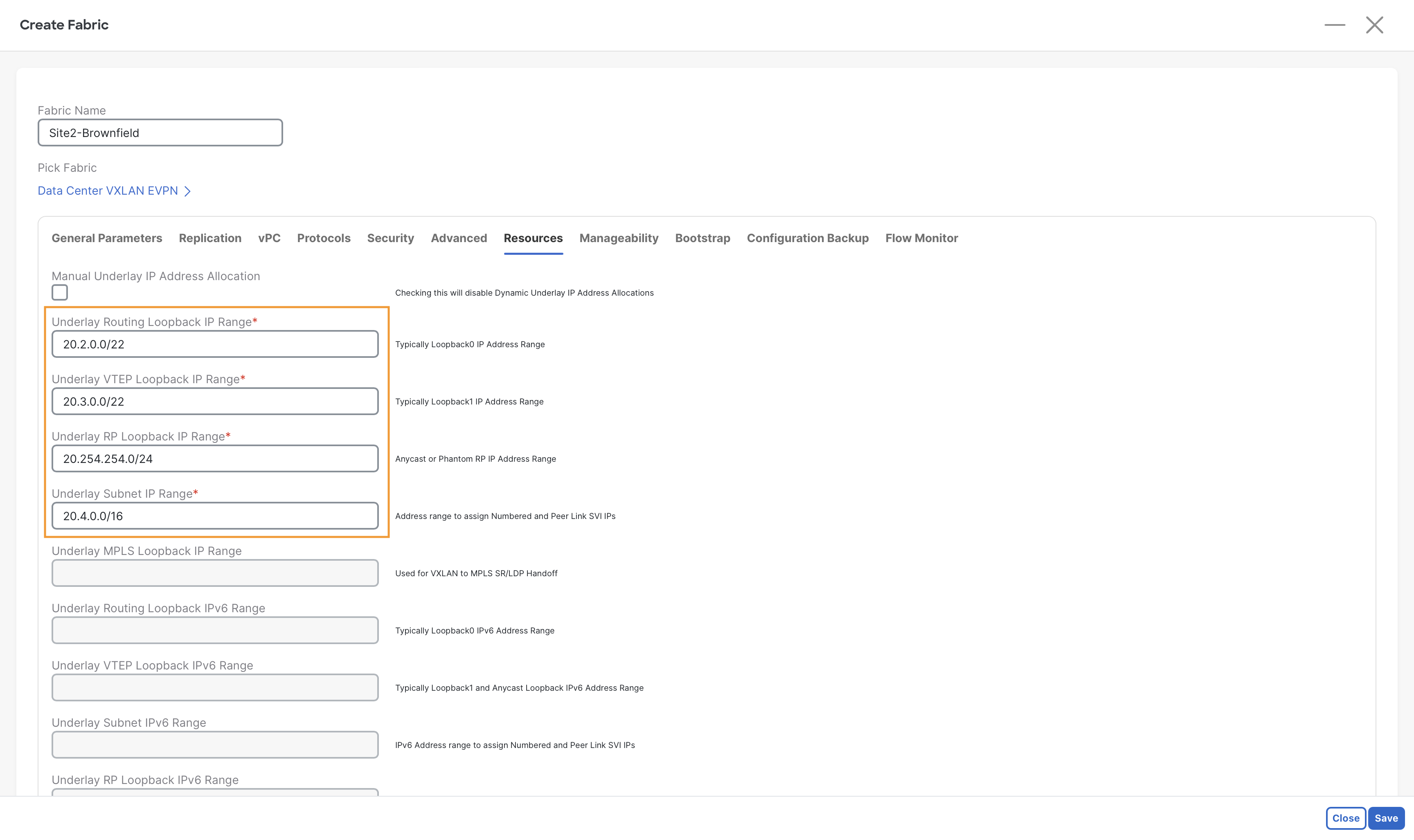
Step 5 - In the Resources tab, define the IP address pools for the Routing Loopbacks, VTEP Loopbacks, Spine RP Loopbacks, and the Physical Interfaces to align with the addressing scheme already used in the Brownfield fabric using the following values:
Tip
Simply replace the first octet with 20, and you will be good
| Parameter | Value | Main Purpose |
|---|---|---|
| Underlay Routing Loopback IP Range | 20.2.0.0/22 | Control Plane Reachability |
| Underlay VTEP Loopback IP Range | 20.3.0.0/22 | Data Plane Reachability (VTEP src/dst) |
| Underlay VTEP RP IP Range | 20.254.254.0/24 | Multicast RP for BUM Replication |
| Underlay Subnet IP Range | 20.4.0.0/16 | P2P subnets for spine-leaf links |
Step 6 – Click on the Save button to create this fabric.
Add Switches to Site2-Brownfield Fabric
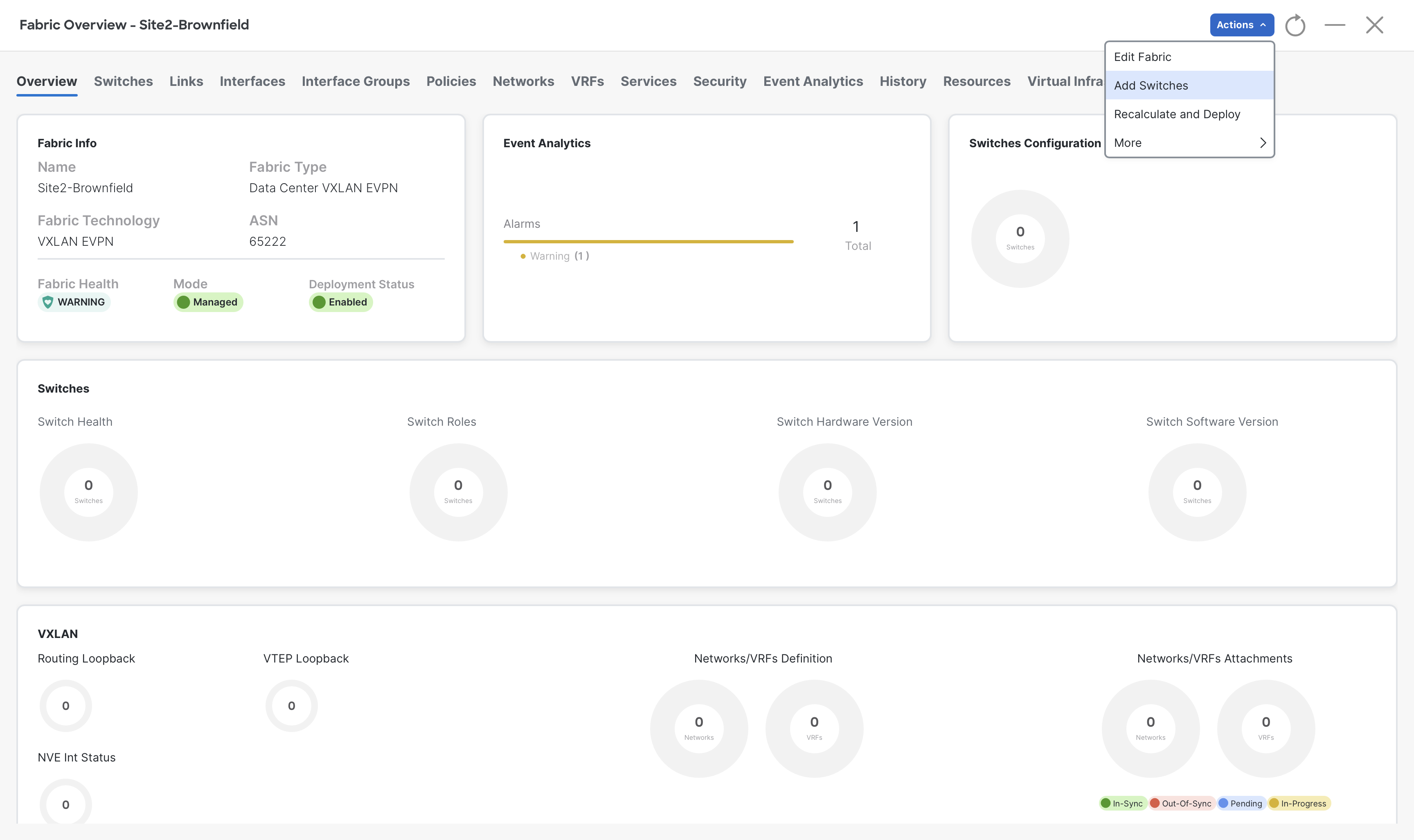
Step 1 - On Fabric Controller page, click Manage > Fabrics and then double-click Site2-Brownfield fabric which you have just created.
Step 2 - In the Fabric Overview page, click Actions > Add Switches.
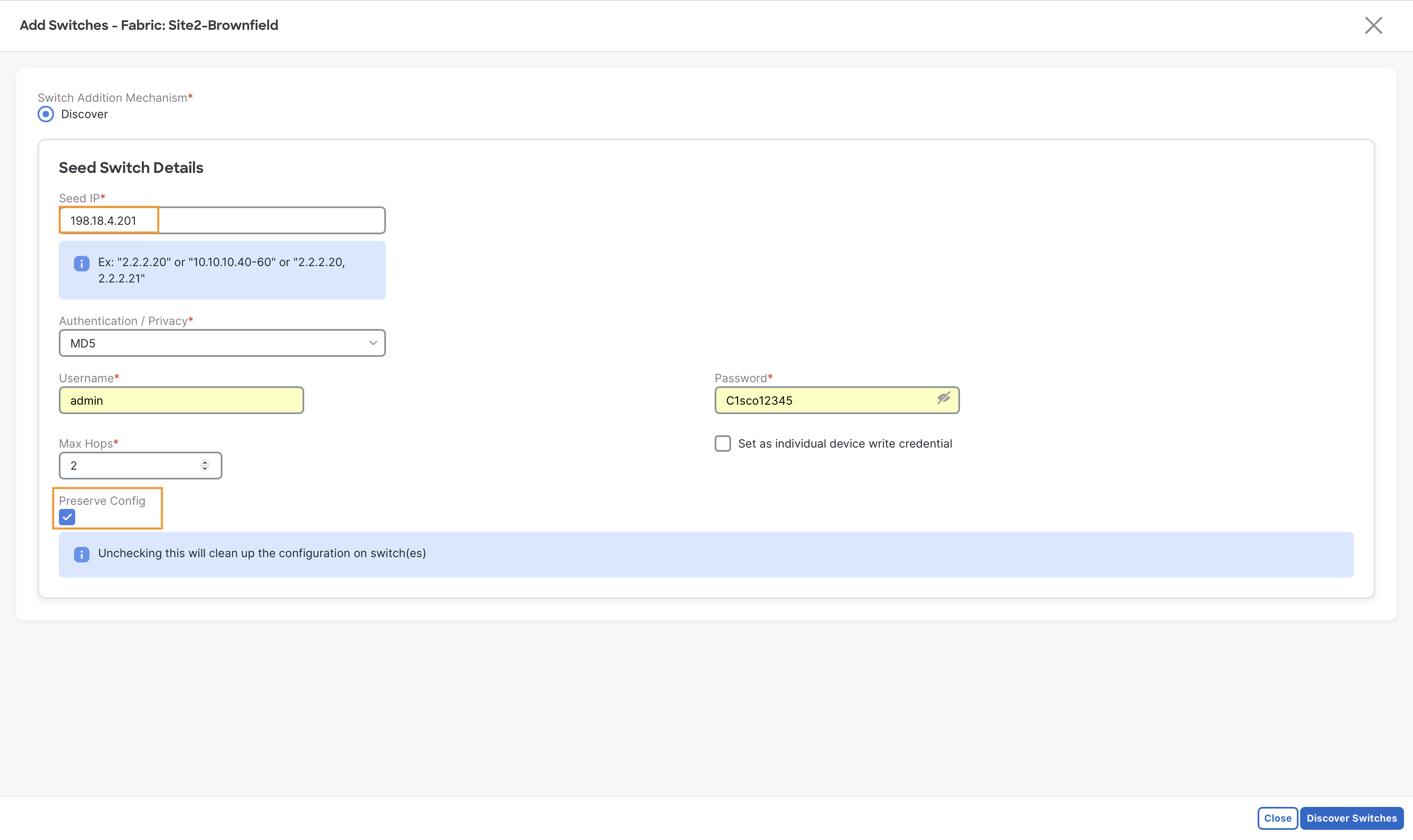
Step 3 - In the Add Switches dialog, in the Seed IP field, enter 198.18.4.201 (Mgmt IP of Site2-Leaf1).
- In the Username field, enter admin.
- In the Password field, enter C1sco12345.
- Make sure to set the Preserve Config toggle to Yes and then click Discover Switches. If you remove it then the existing configuration will be wiped.
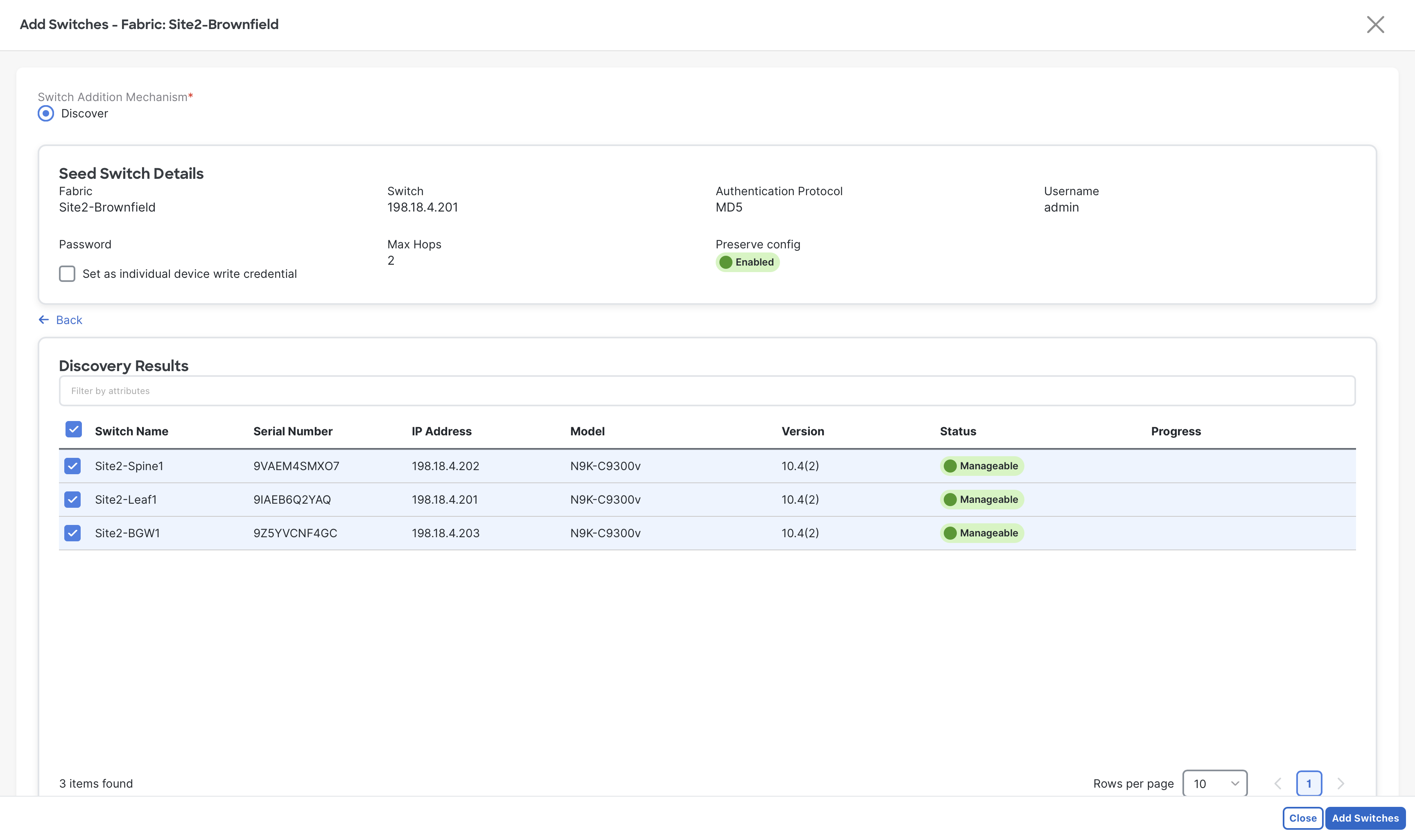
Step 4 - Check the select all check box and then click Add Switches.
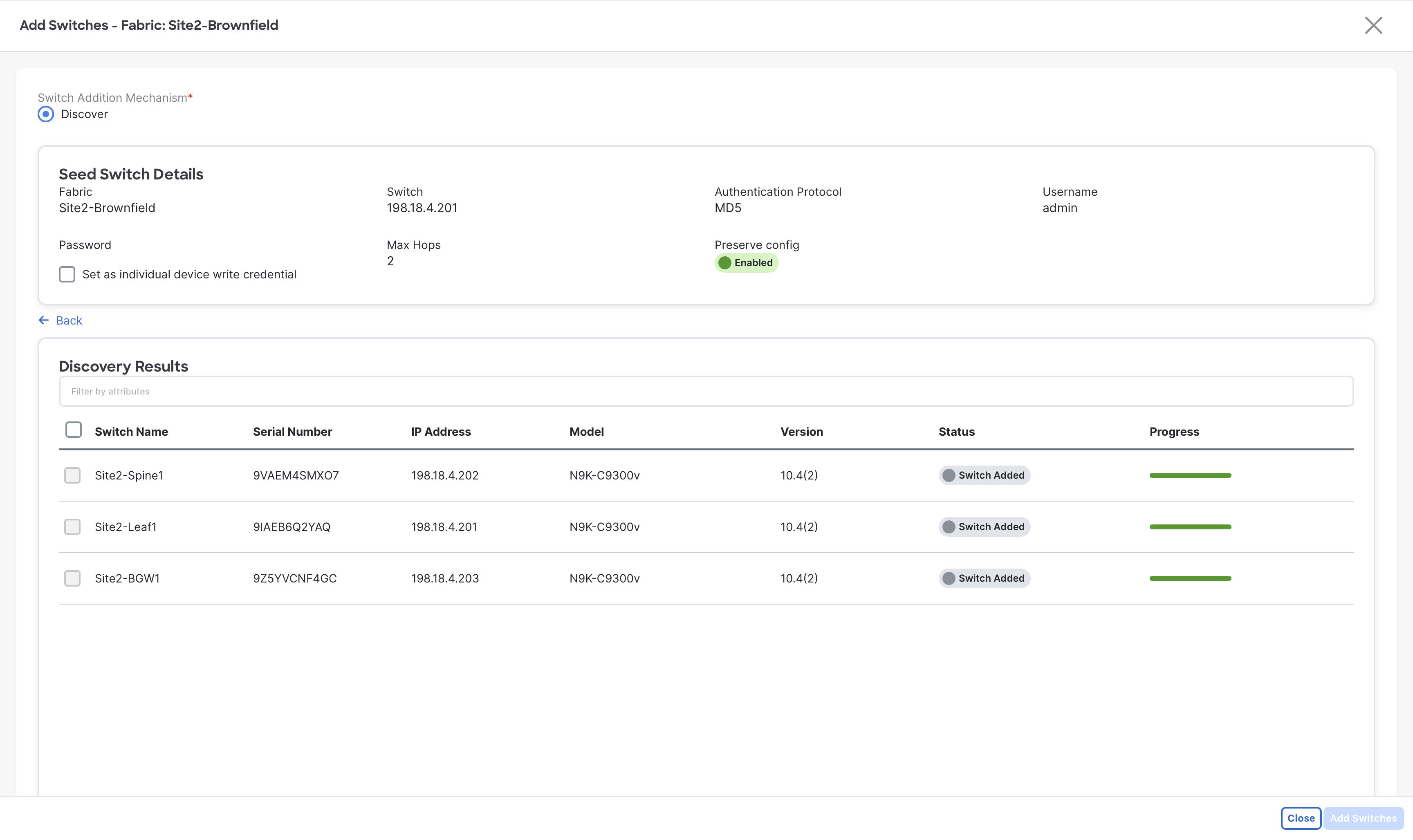
Step 5 - When the import completes, click Close.
Step 6 – To display the list of onboarded switches, click the Switches tab.
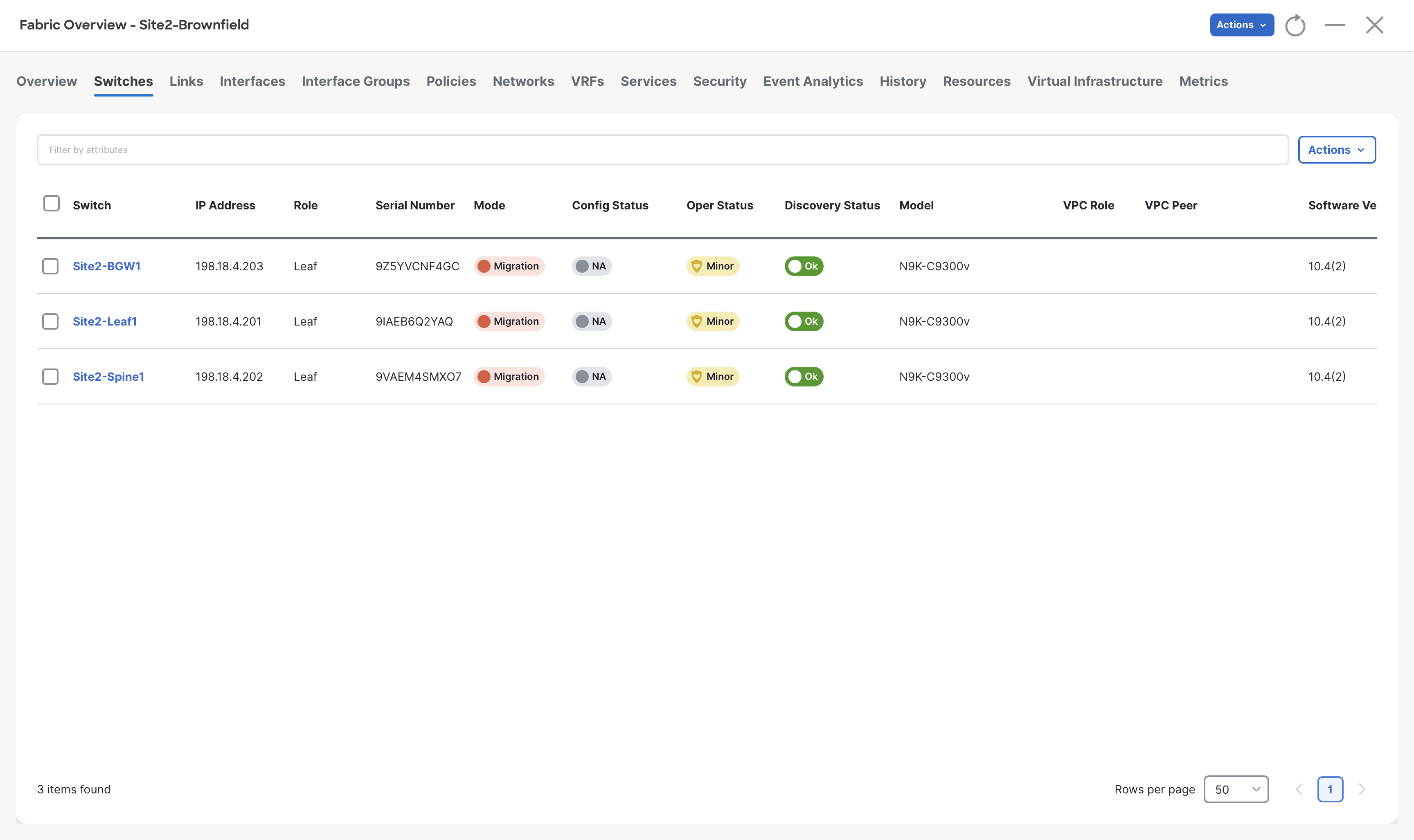
Note
NDFC automatically assigns the role based on the device model. Since all three devices are of the same model, NDFC sets them to the Leaf role.
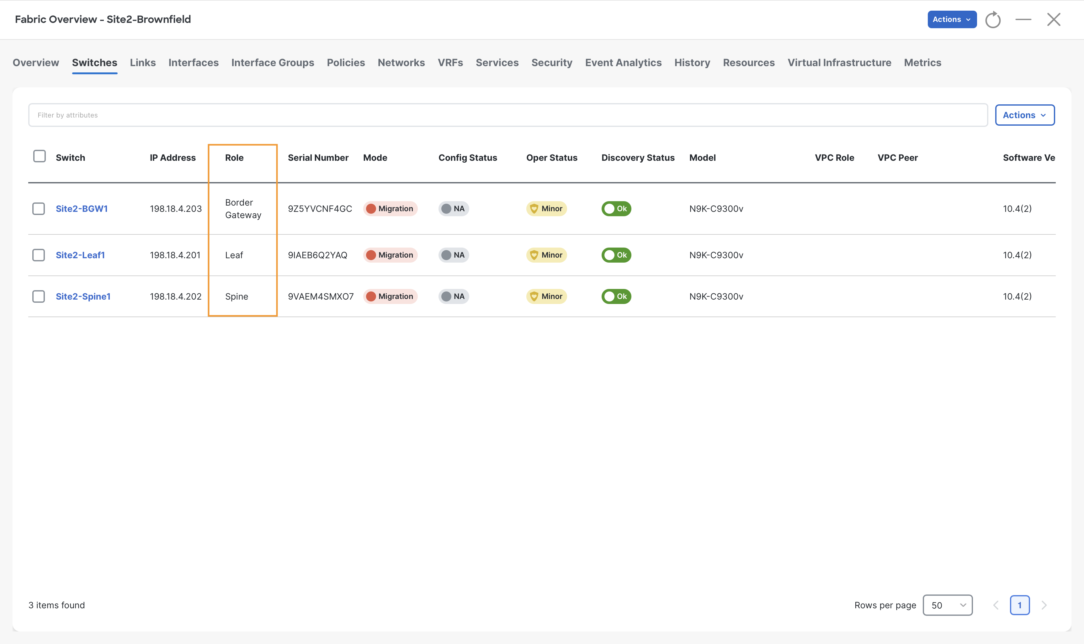
Step 7 – To set the desired role for switches, click the box next to the switch and then select role from Actions > Set Role.
When the Recalculate Config warning displays, click Ok.
- Set Site2-BGW1 to Border Gateway role.
- Set Site2-Spine1 to Spine role.
Step 8 – In the Fabric Overview window, click Actions > Recalculate and Deploy.
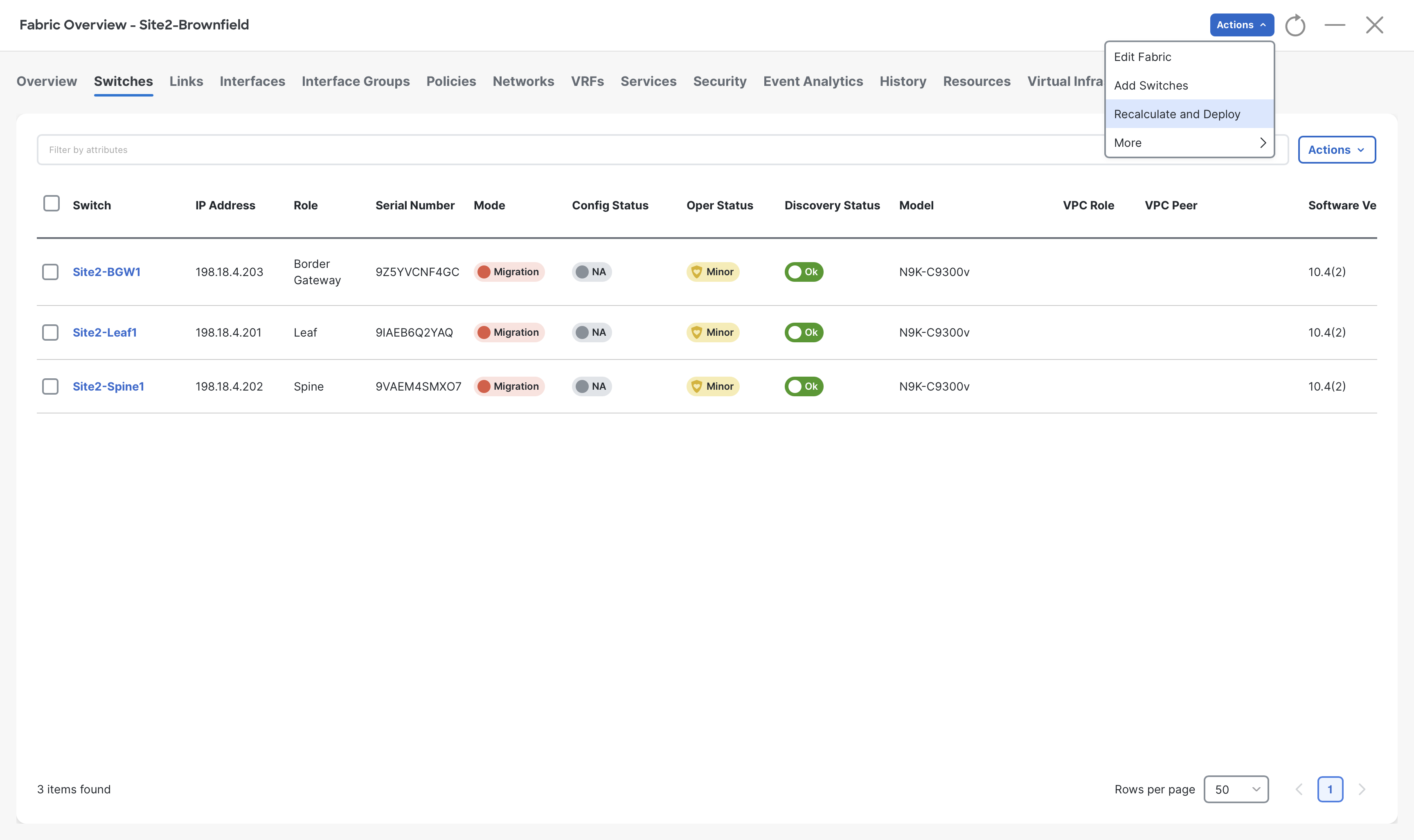
After you click Recalculate and Deploy, NDFC renders the required configuration that is based on:
- Cisco Best Practices and Validated Designs templates
- Your user input when you initially created the fabric
- The Brownfield configuration
In the Deploy Configuration wizard, you will see that only a few lines of configuration are required for the Brownfield fabric devices. These lines are to bring your Brownfield fabric into alignment with NDFC intent. After inspecting them you will notice that the only additional configuration will be pushed to ensure that SNMP traps will be sent to NDFC. This is a setting defaulted to True, but could also be disabled in each fabric.
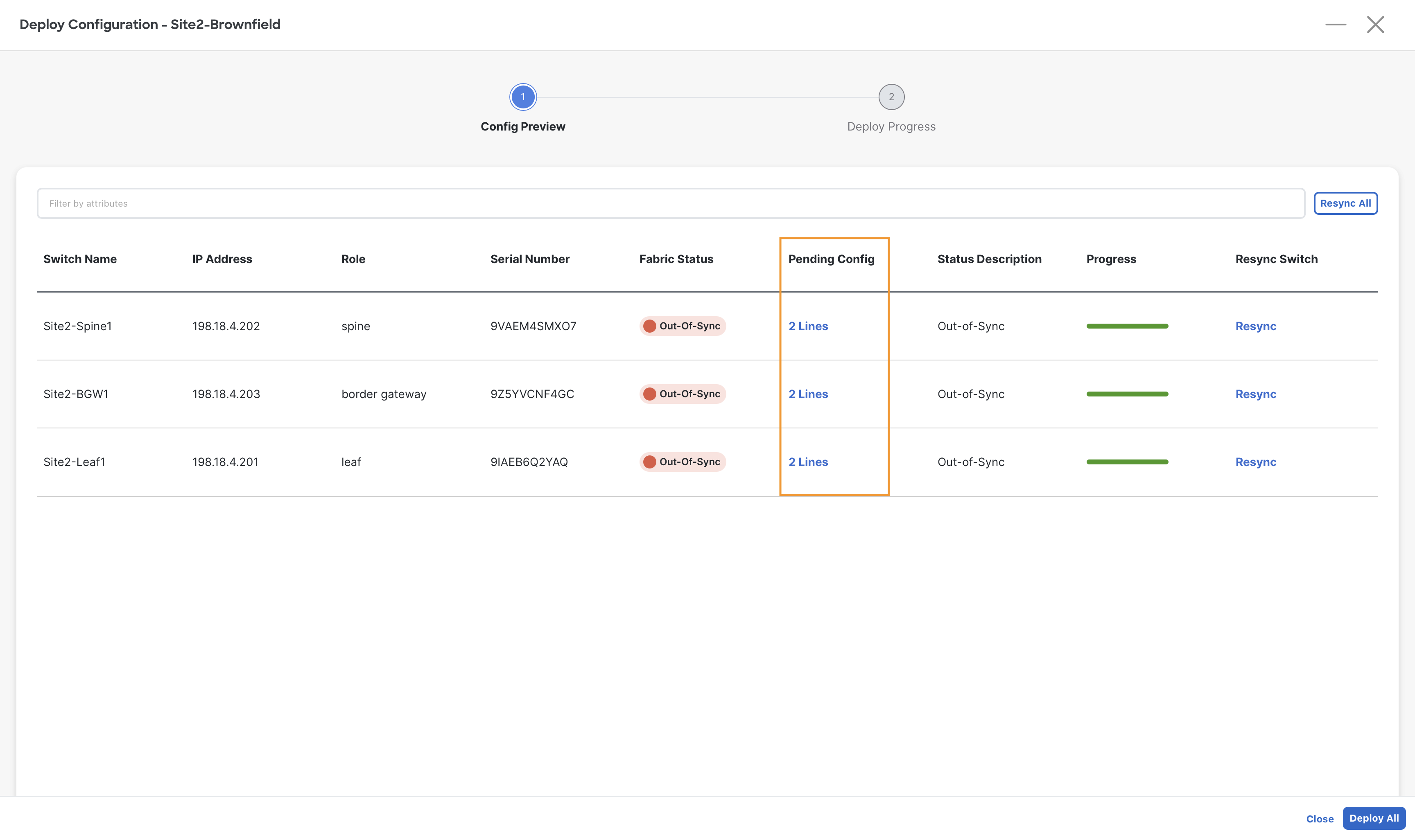
Step 9 – Click Deploy All.
Step 10 – Once deployment is completed, click Close.
Review VRFs and Networks
Step 1- Navigate to VRFs tab of Site2-Brownfield fabric and review the VRFs imported from your Brownfield fabric
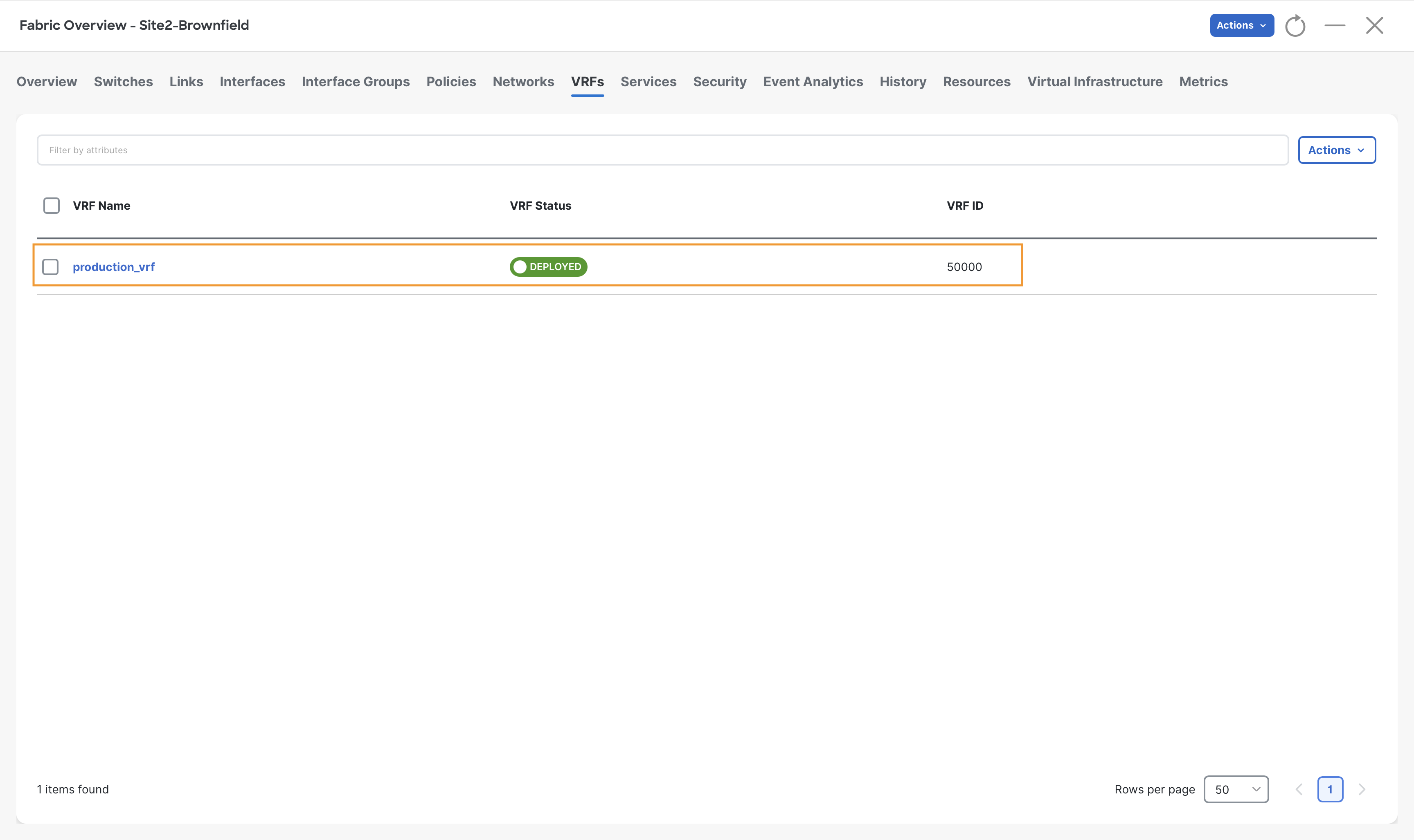
a) In the top navigation, click VRFs.
You will find production_vrf VRF imported from the Site2-Brownfield fabric to NDFC.
b) To review the VRF Attachments, double-click on production_vrf, then click VRF Attachments tab on the VRF Overview page.
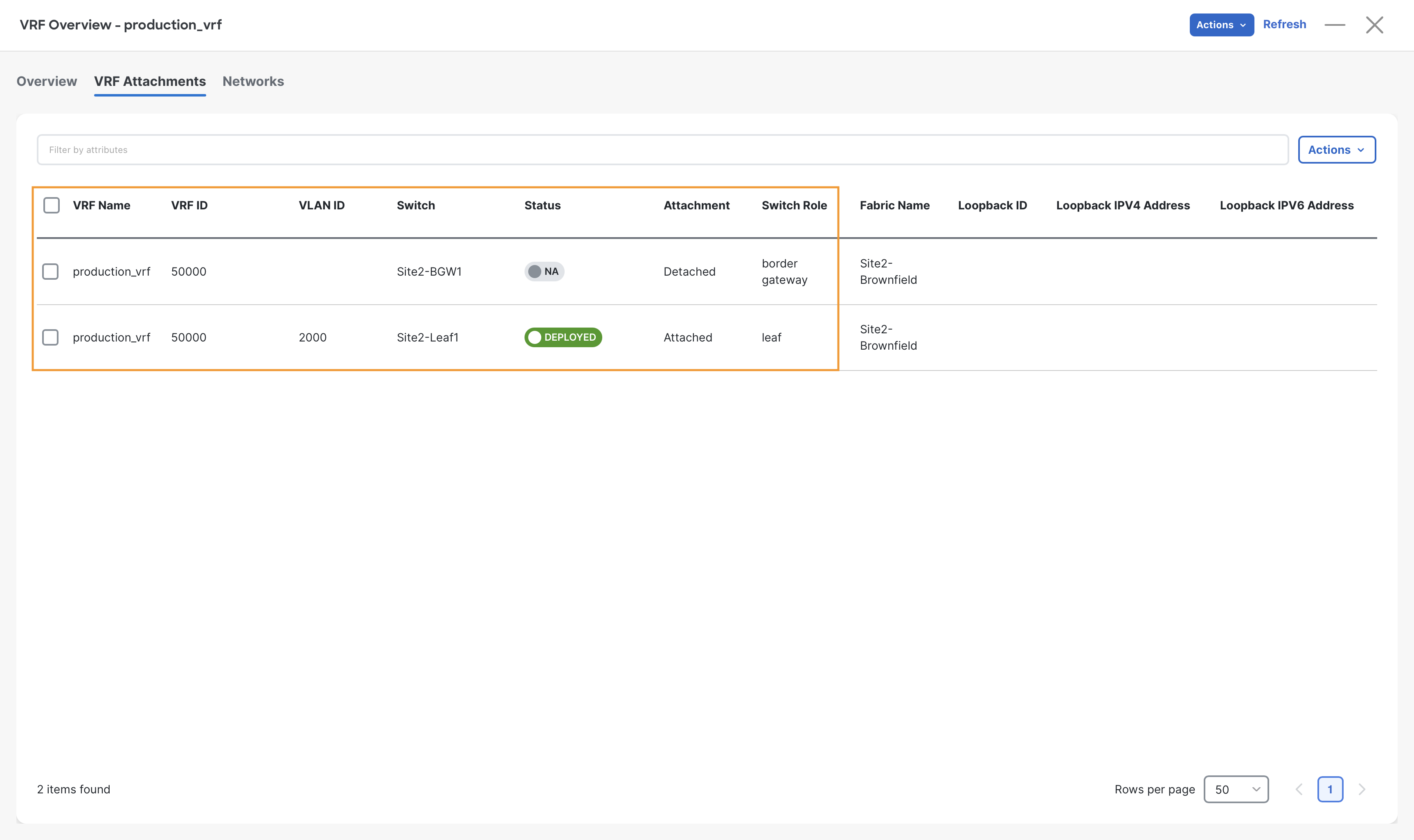
The production_vrf is shown as deployed to the Site2-Leaf1 switch and is associated with VLAN 2000. This VLAN is the VTEP local interface that will be used for routing traffic across different networks, part of the same VRFs.
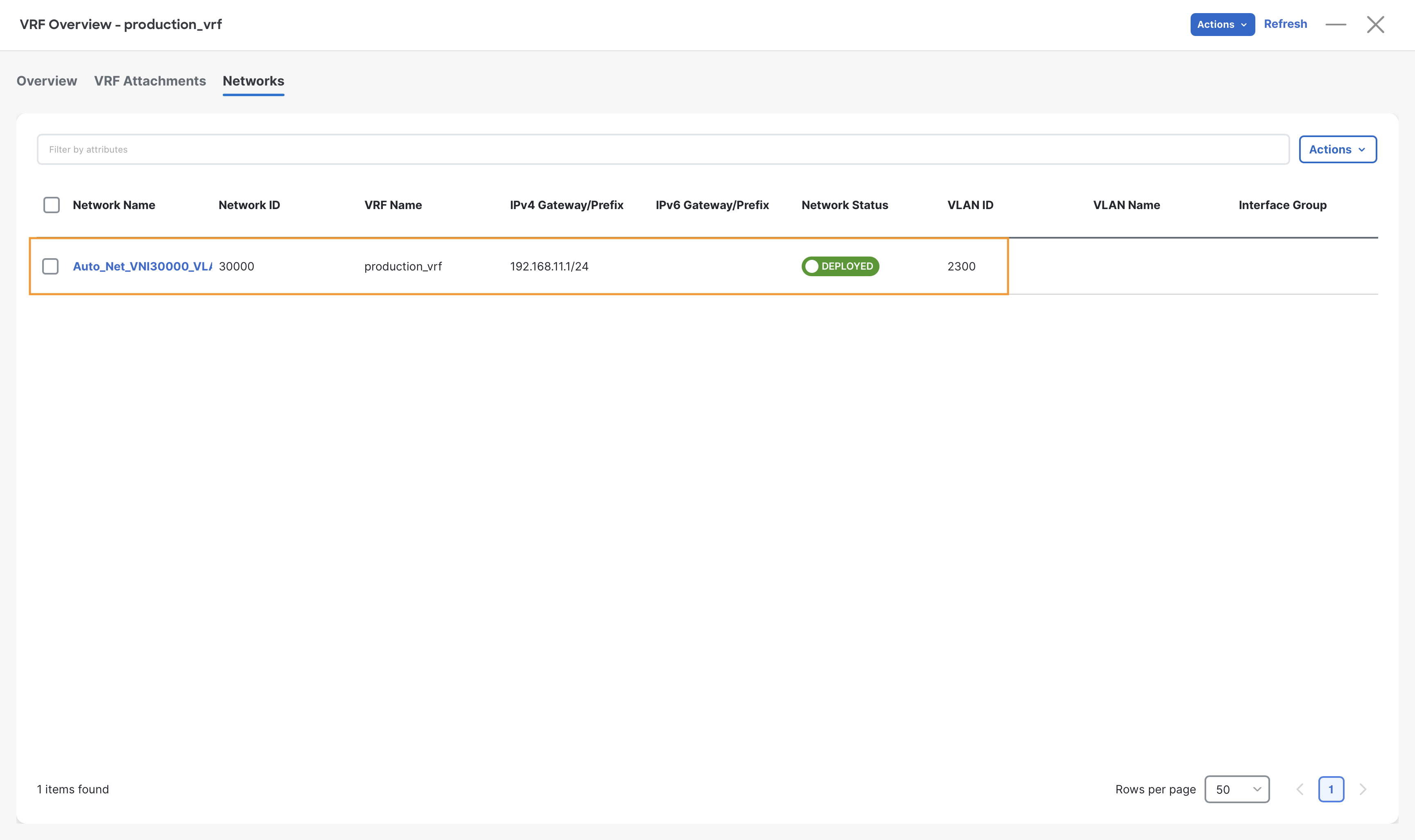
Step 2 - To review Networks, click Networks on the VRF Overview page. We see one network imported from the Brownfield fabric.
The Networks are named with a prefix of Auto_Net_VNI. This name signifies a Network that is imported as part of a Brownfield import. The prefix is not fixed and can be decided by the administrator before importing the brownfield site. After importing, its name can be changed if desired.
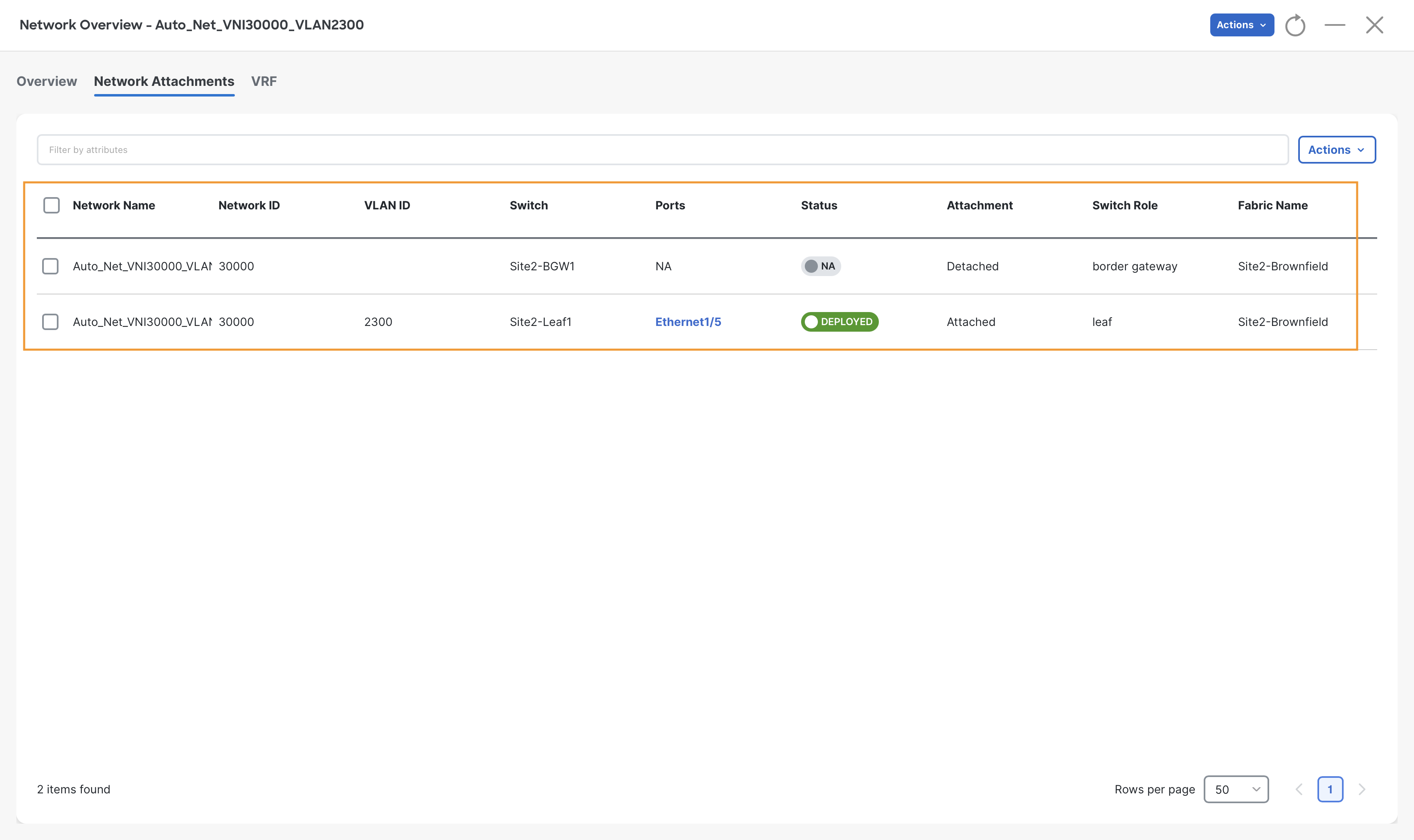
To review the Network Attachments, double-click on the Auto_Net_VNI imported netowork and then click Network Attachments tab on the Network Overview page
Verify Site2-Brownfield Fabric
Step 1 - Verify Site2-Spine1 BGP EVPN neighbors.
Open MPuTTy, log in to Site2-Spine1, and run the command show bgp l2vpn evpn summary.
Site2-Spine1
show bgp l2vpn evpn summary
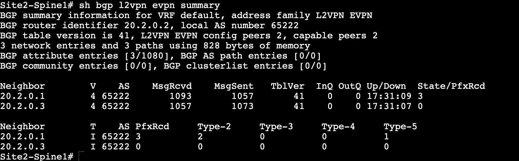
Step 2 – Observe the output, Site2-Spine1 should have two neighbors (Site2-Leaf1 & Site2-BGW1) for the L2VPN EVPN address family.
From the above output, we see that Site2-Leaf-1 is advertising three EVPN prefixes.
Step 3 – (Optional) To see the EVPN prefixes learned on Site2-Spine1, run the command show bgp l2vpn evpn.
Site2-Spine1
show bgp l2vpn evpn
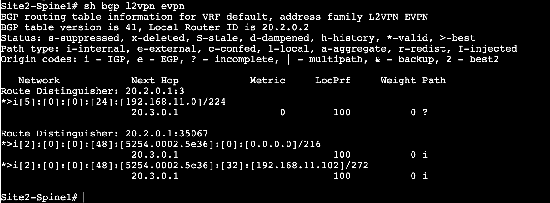
In the above output, we see that Site2-Spine1 has received three EVPN routes from Site2-Leaf1.
Note
You might see diffrent MAC address for the Servers as it is unique to every POD.
You can continue now with Task #3