Lab 3 - Create the Multi-Site Domain
Import and Deploy an ISN Fabric
With your Site1-Greenfield and Site2-Brownfield VXLAN fabrics created and verified as configured and functioning correctly, the next step is to build VXLAN Multisite connectivity between the two fabrics. VXLAN Multisite allows extending L2 domains and provides L3 connectivity between two or more VXLAN fabrics. To build VXLAN Multisite, NDFC offers the VXLAN EVPN Multi-Site template.
Info
Various design and deployment strategies exist for VXLAN Multi-Site configurations. In this lab, you will set up a Site-External network across a routed domain. To summarize, the Border Gateways from both fabrics will be linked via a Layer 3 network. For our purposes, this Layer 3 network will be emulated using a single Nexus device; however, in real-life scenarios, it could extend across multiple routers and networks, provided there is connectivity and support for an increased MTU. It is important to account for an additional 54 bytes on top of the frame size forwarded by the end-hosts to ensure proper encapsulation and transmission.
For our use case, you must create an External fabric for the router that act as the Inter-Site Network (ISN) providing connectivity between your data center sites. This router will also provide the Route Server functionality which will relax the requirement for full mesh MP-BGP EVPN sessions across all Border Gateways. Consider the Route-Server as a Route-Reflector BGP speaker which supports sessions with different Autonomous Systems.
NDFC will provide full automation and orchestration support for the External fabric too, isn't that great?
Create External Fabric
Step 1 - On Fabric Controller page, click on Manage > Fabrics and then select Create Fabric from Actions drop-down
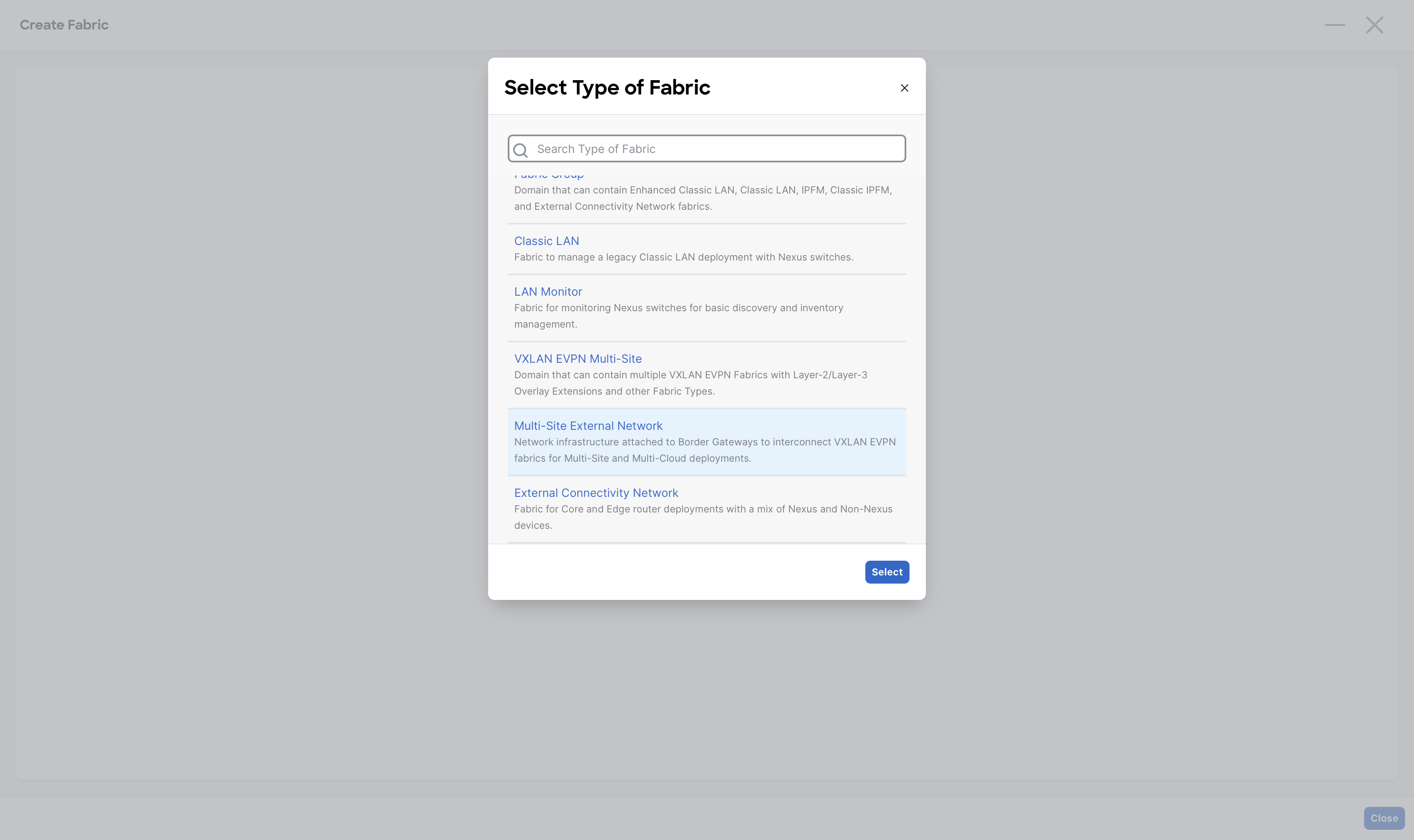
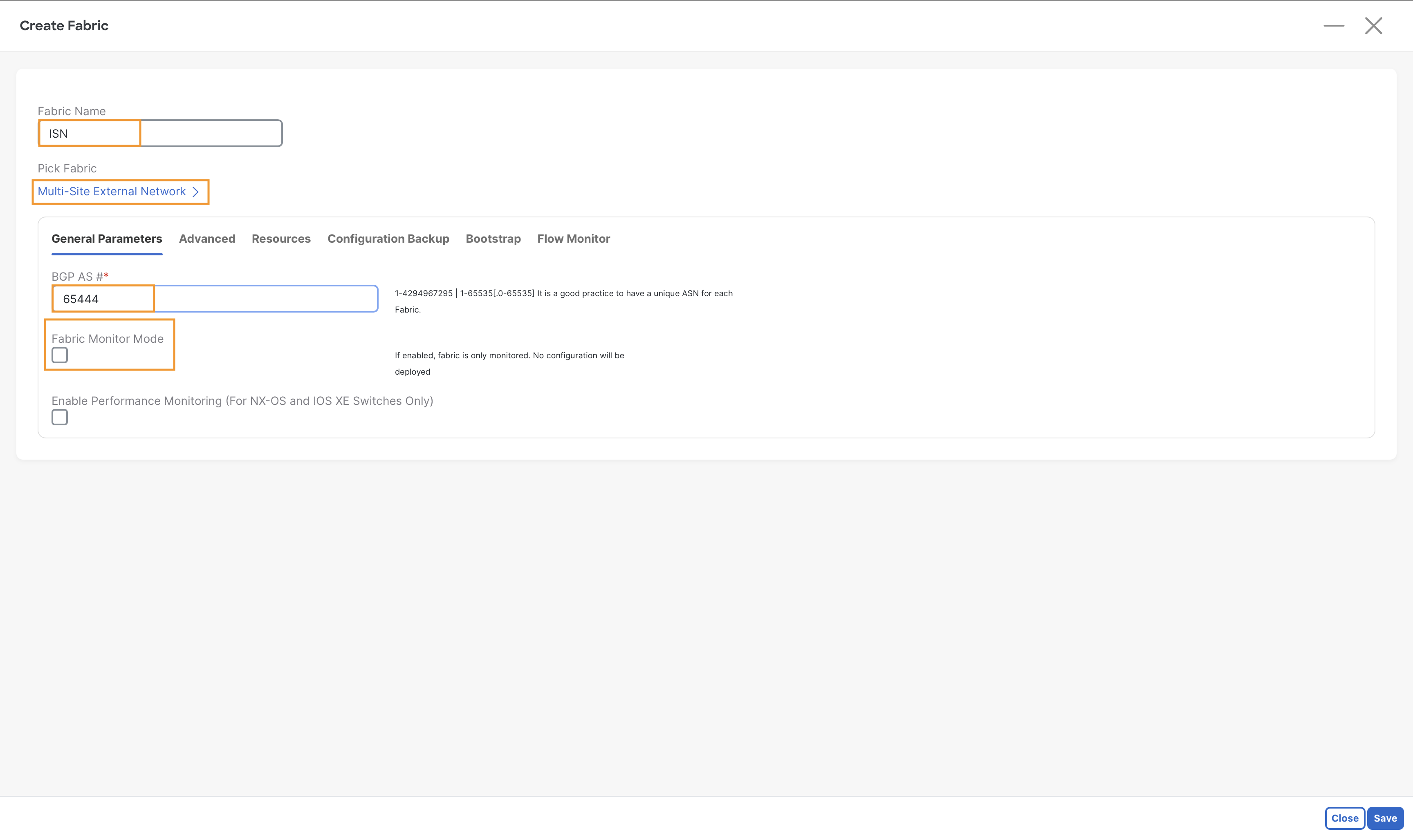
Step 2 - In the Fabric Name field, enter ISN then click Choose Fabric and select Multi-Site External Network
Step 3 - In the General tab, in the BGP AS # field, enter 65444
Step 4 - Deselect the Fabric Monitor Mode check box and then click Save
Add The Switches
Step 1 - From Fabric Controller page click Manage > Fabrics and double-click on ISN fabric and then click Actions > Add Switches
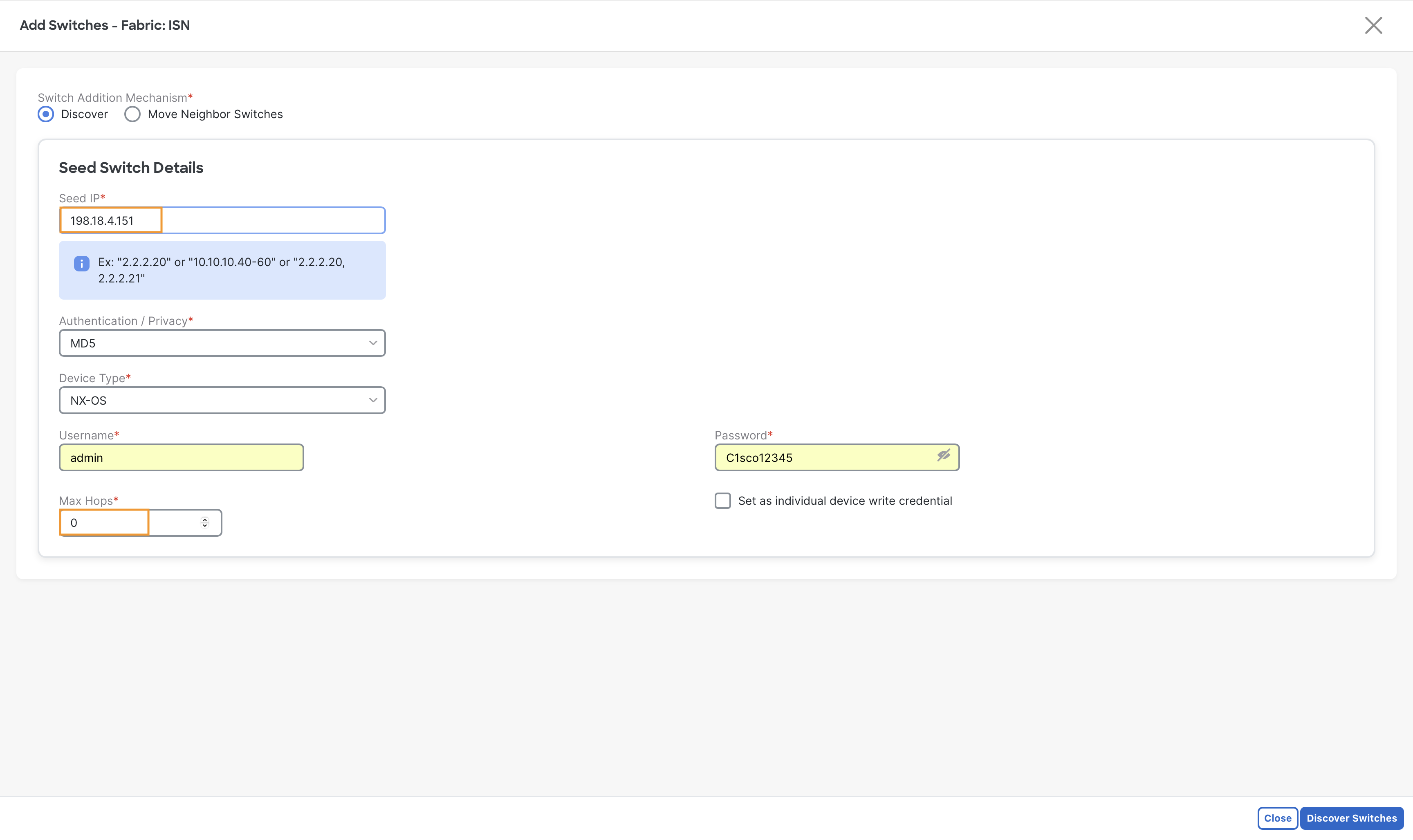
Step 2 - In the new window, in the Seed IP field, enter 198.18.4.151
- In the Username field, enter admin
- In the Password field, enter C1sco12345
- Set Max hops to 0 – This will prevent NDFC from learning unnecessary neighbor devices
Then click Discover Switches
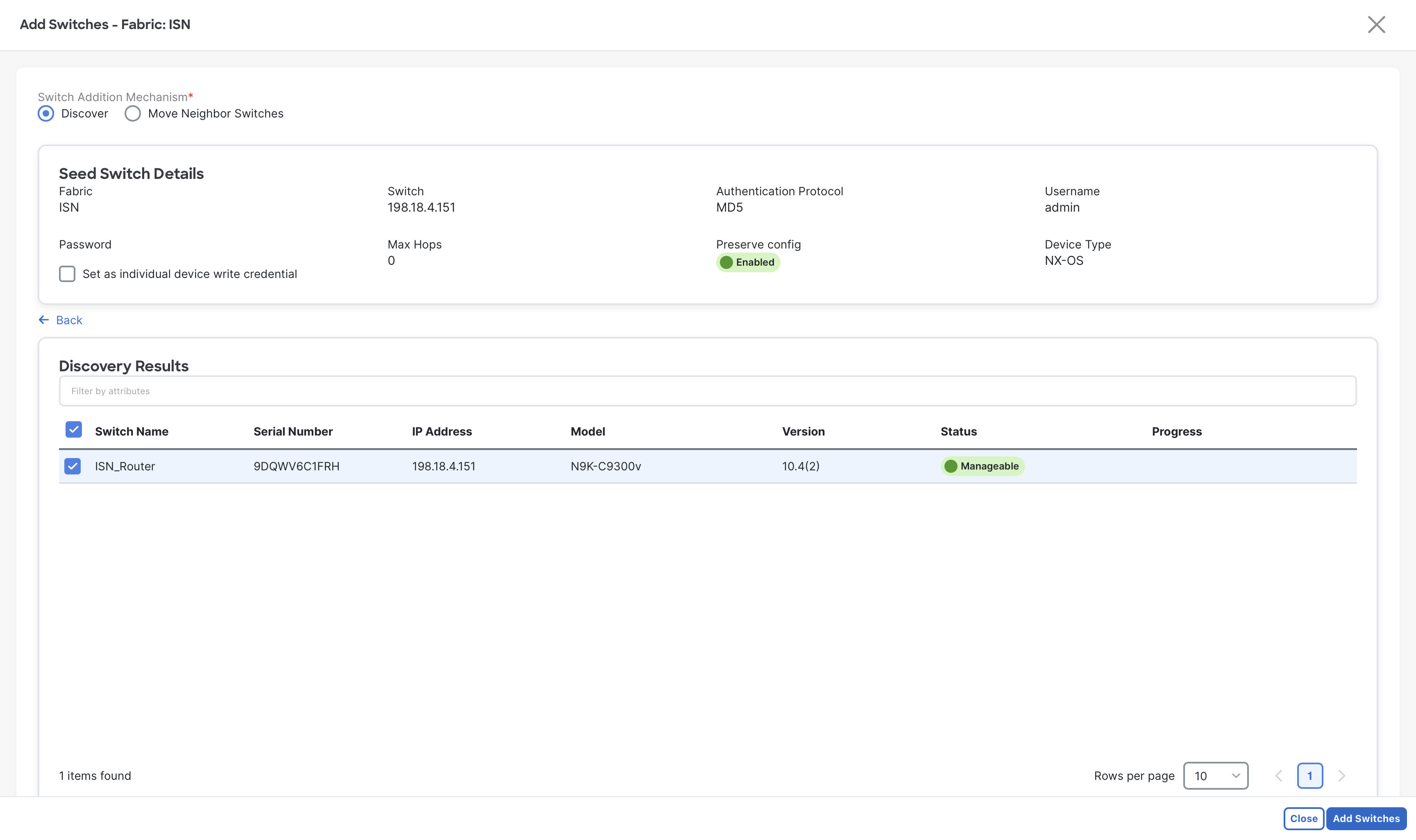
Step 3 - Select ISN_Router and then click Add Switches
Step 4 - When the import completes, click Close
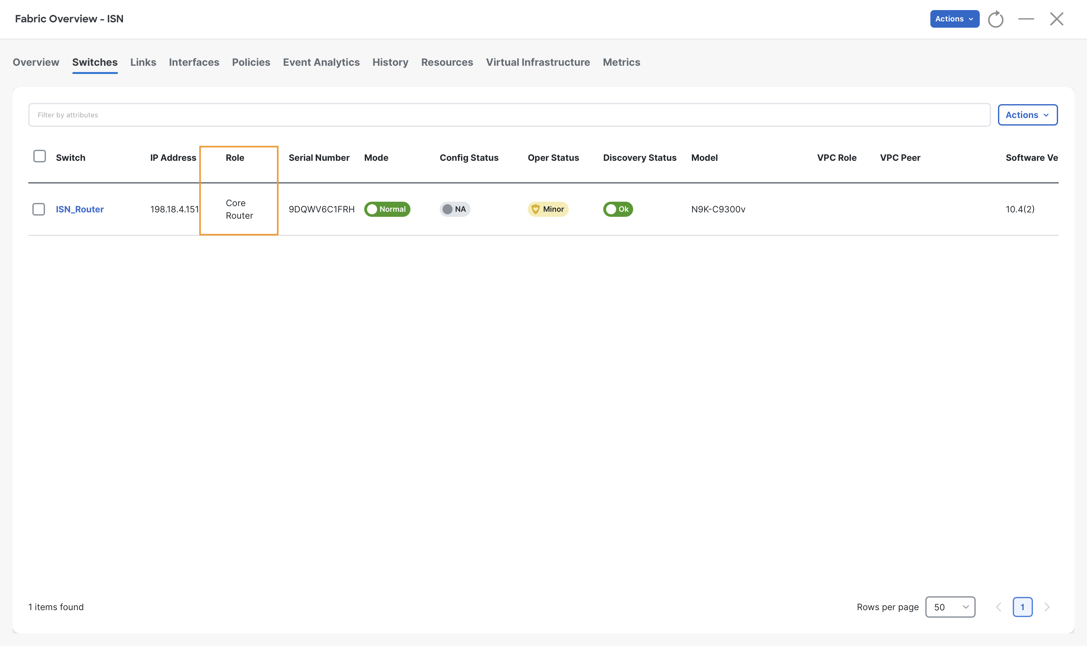
Step 5 - Go to Switches tab of ISN fabric and select ISN_Router and then click Actions > Set role and choose the Core router role and then click Select
When the warning displays about recalculate config, click Ok
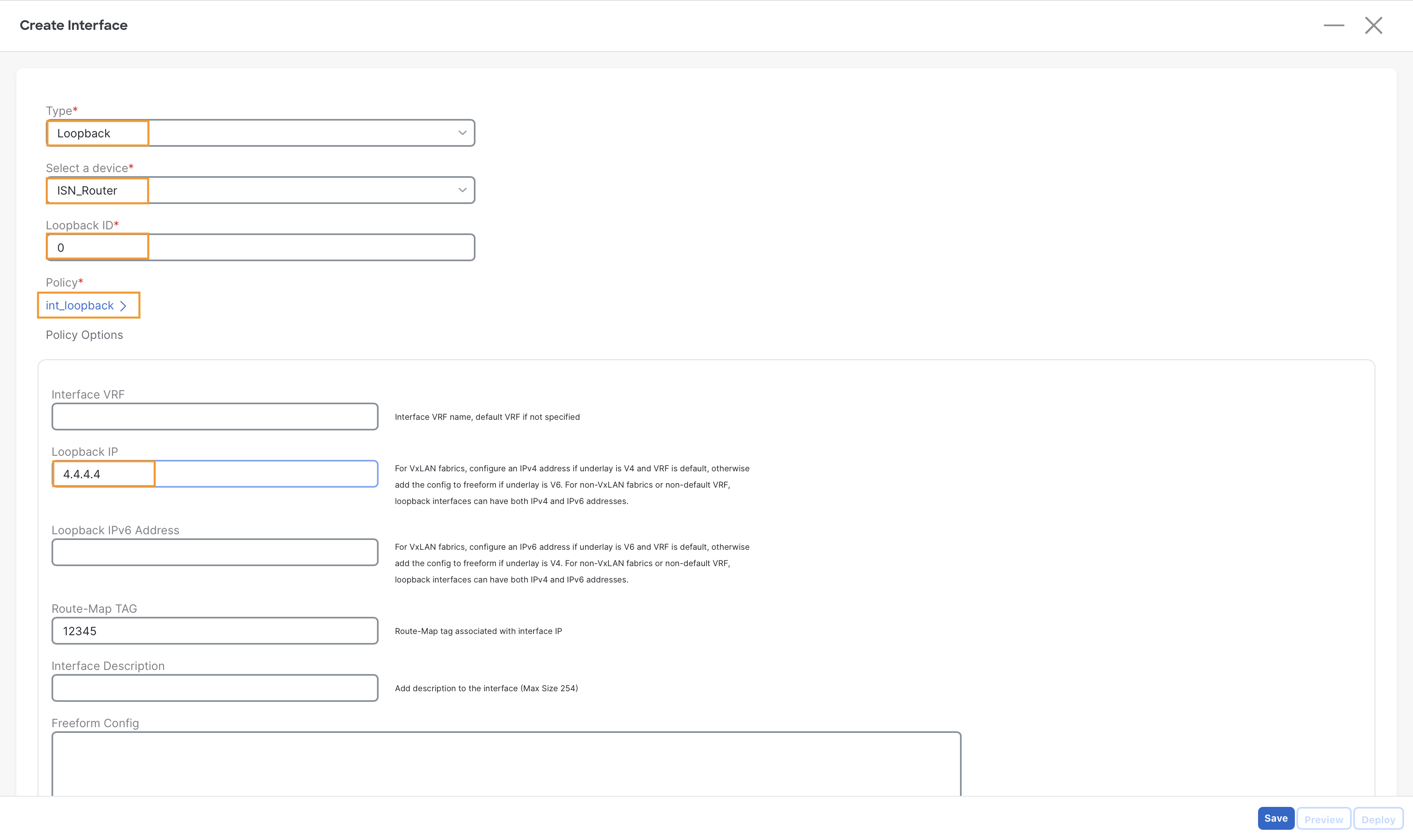
Step 6 – Now create a loopback interface on ISN_Router with the following parameters:
- Type – loopback
- Select a device – ISN_Router
- Loopback IP – 4.4.4.4
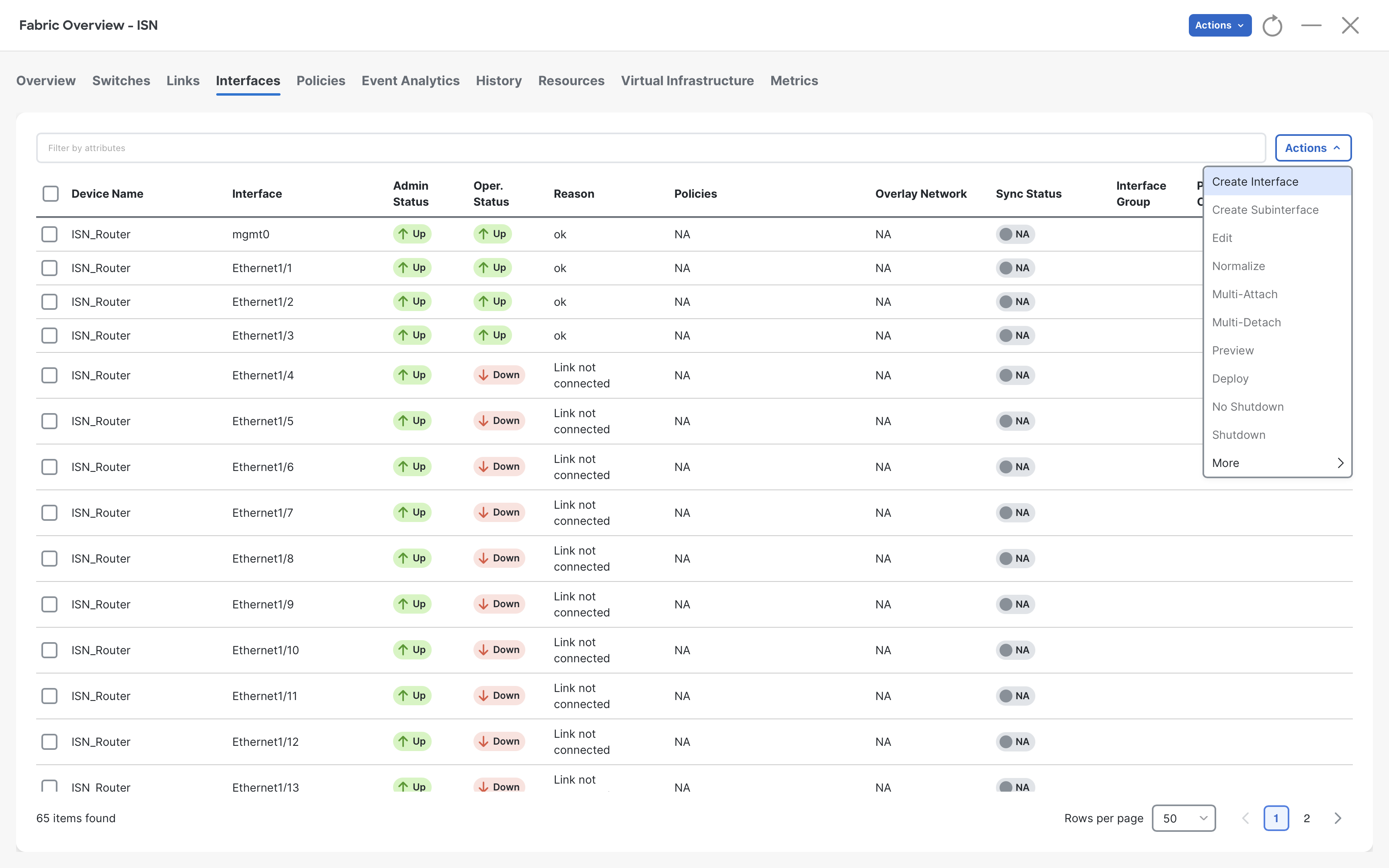
To create interface, go to Interfaces tab of ISN fabric and select Create Interfaces from Actions drop-down
Tip
This loopback will be used for the Route-Server functionality. It will be required while building Overlay BGP peering (EVPN) for VXLAN Multisite.
Step 7 – Click Save and close the Create Interface dialog from the top
Note
The interface configuration will be deployed in the next step.
Step 8 - On the Fabric Overview page click Actions > Recalculate and Deploy
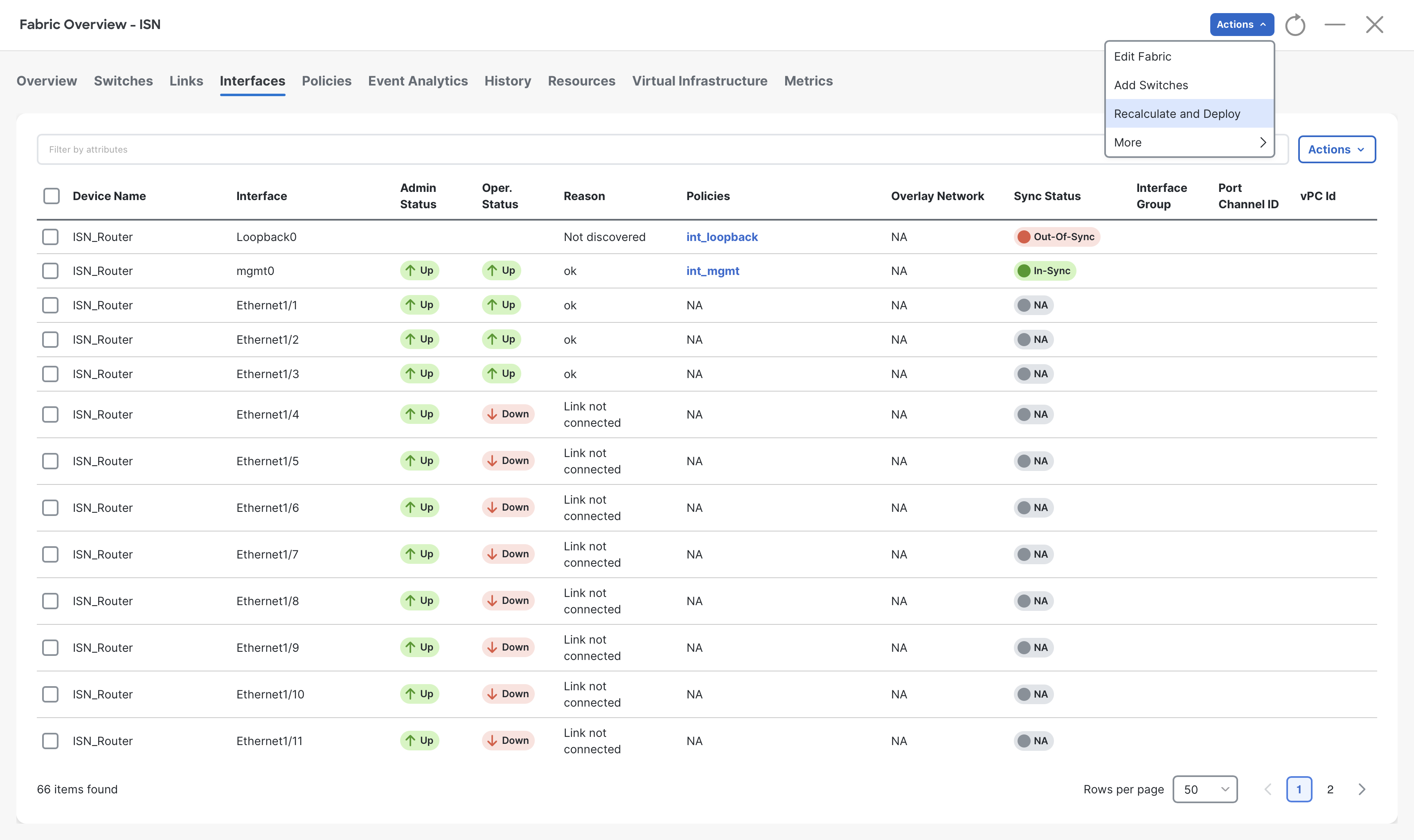
Step 9 - Click Deploy All and then, when the status changes to SUCCESS, click Close
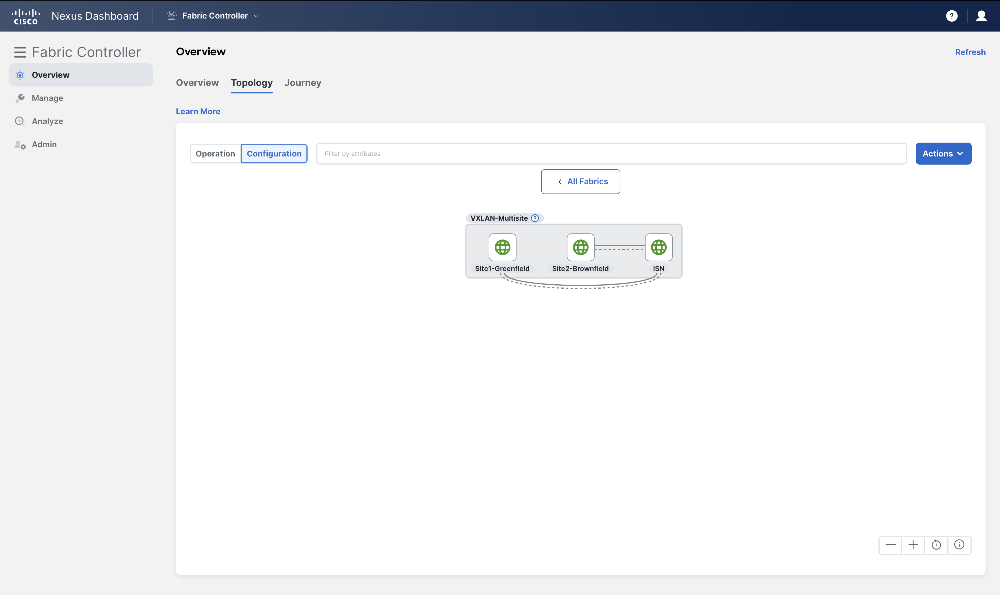
Step 10 – On Fabric Controller page, click Overview and go to Topology tab and then change the view mode to Configuration
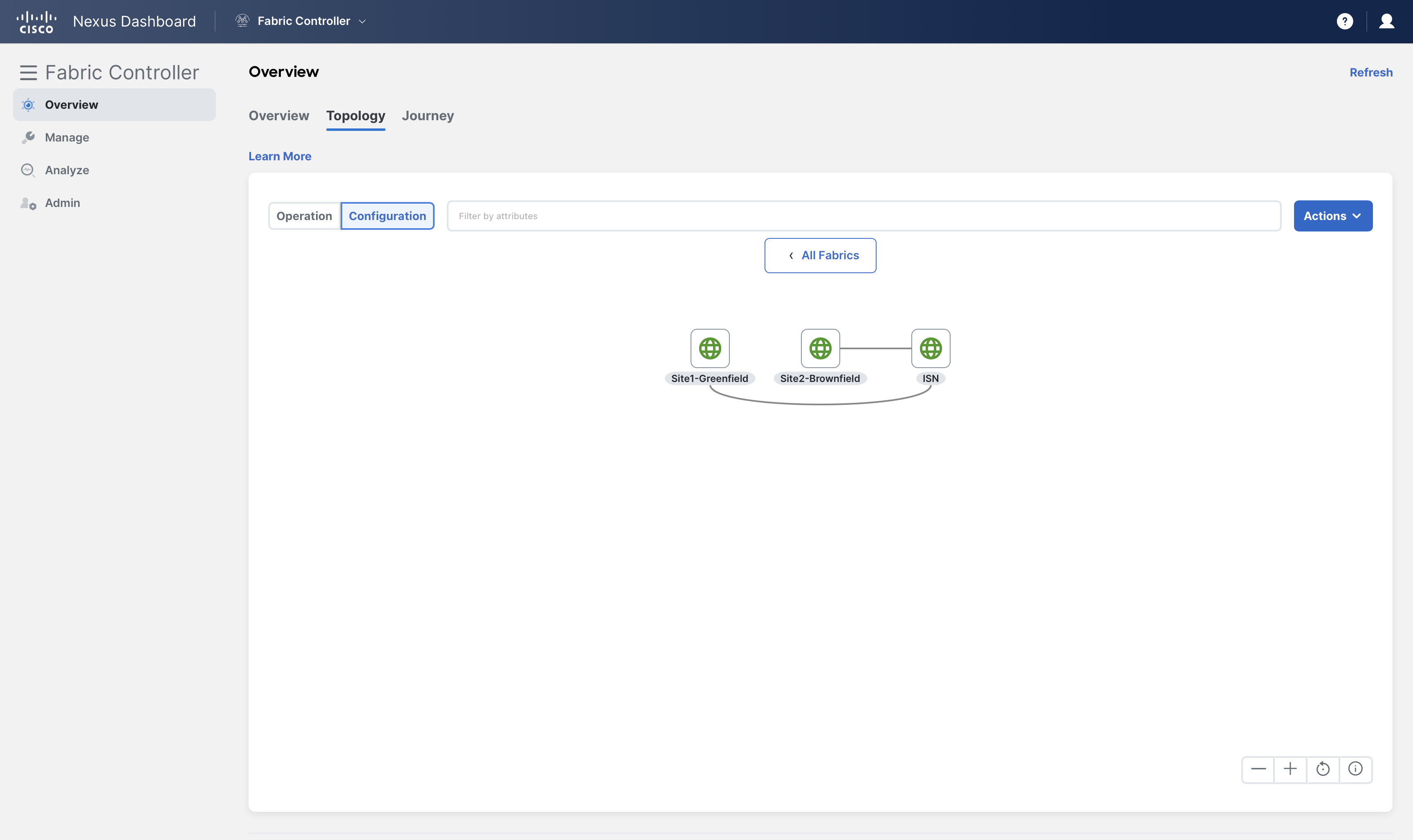
Now we should have a total of three fabrics, two VXLAN fabrics: Site1-Greenfield, Site2-Brownfield and one External fabric ISN.
Observe in the topology how NDFC already knows about the interconnections among them. This is thanks to the discovery process which can build an adjacency map based on the CDP tables.
Configure VXLAN Multisite
In this section, we will create a multisite fabric using the VXLAN Multi-Site (also known as MultiSite Domain or MSD) template in NDFC. Then we import all three fabrics with an easy-to-use NDFC GUI and build VXLAN Multisite connectivity between the individual VXLAN fabrics.
And finally, perform a Ping test between servers in two different sites to confirm that the multisite is configured successfully.
Create Fabric
Step 1 - On Fabric Controller page, click on Manage > Fabrics and then click Actions > Create Fabric
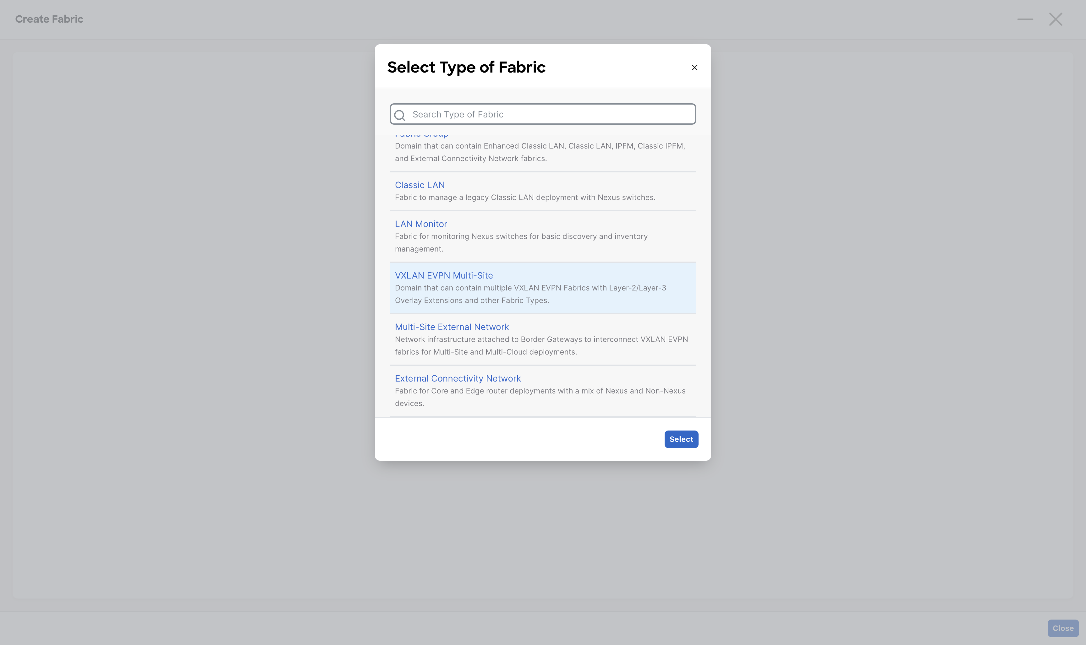
Step 2 - In the Fabric Name field, enter VXLAN-Multisite, then click Choose Fabric and select the VXLAN EVPN Multi-Site fabric template and then click Select
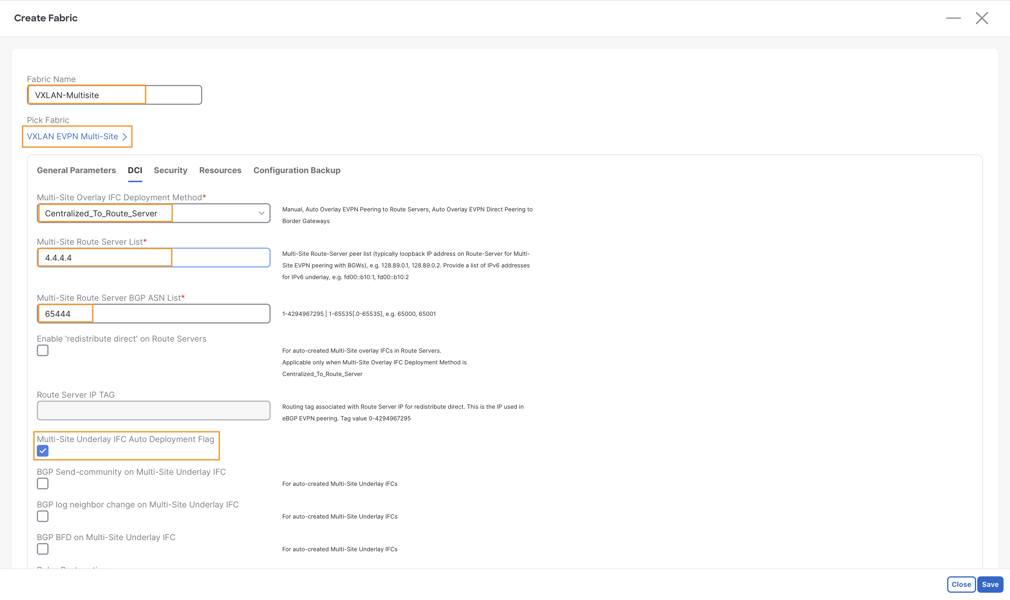
Step 3 - Configure DCI
Change the following options in the Fabric Settings -
- Under DCI tab, in the Multi-Site Overlay IFC Deployment Method drop-down, select Centralized To Route Server option
- In the Multi-site Router Server List field, provide the IP Address 4.4.4.4 configured on Loopback0 interface of the ISN Router
- In the Multi-Site Route Server BGP ASN List field, provide the BGP ASN 65444 for the ISN external fabric
- Click the Multi-Site Underlay IFC Auto Deployment Flag checkbox
Info
Under the DCI tab of the VXLAN EVPN Multi-Site template, you can specify the method of configuring the DCI. NDFC supports the following three Multi-Site overlay Inter-Fabric Connections (IFCs) options –
- Manual - Will require you to manually define the MP-BGP EVPN sessions for the overlay
- Using a Route-Server - Will setup all the BGW MP-BGP EVPN sessions towards an external router server
- Directly to the Border Gateways - Will build a full mesh of MP-BGP EVPN sessions between the Border Gateways
In this demo, you deploy the Multi-Site using a Route-Server. The Router-Server, which you already configured in the previous steps, provides DCI connectivity between two VXLAN sites and participates in the EVPN Control-Plane. NDFC provides complete and end-to-end automation for Route-Server based VXLAN Multisite deployment.
Step 4 – Click Save
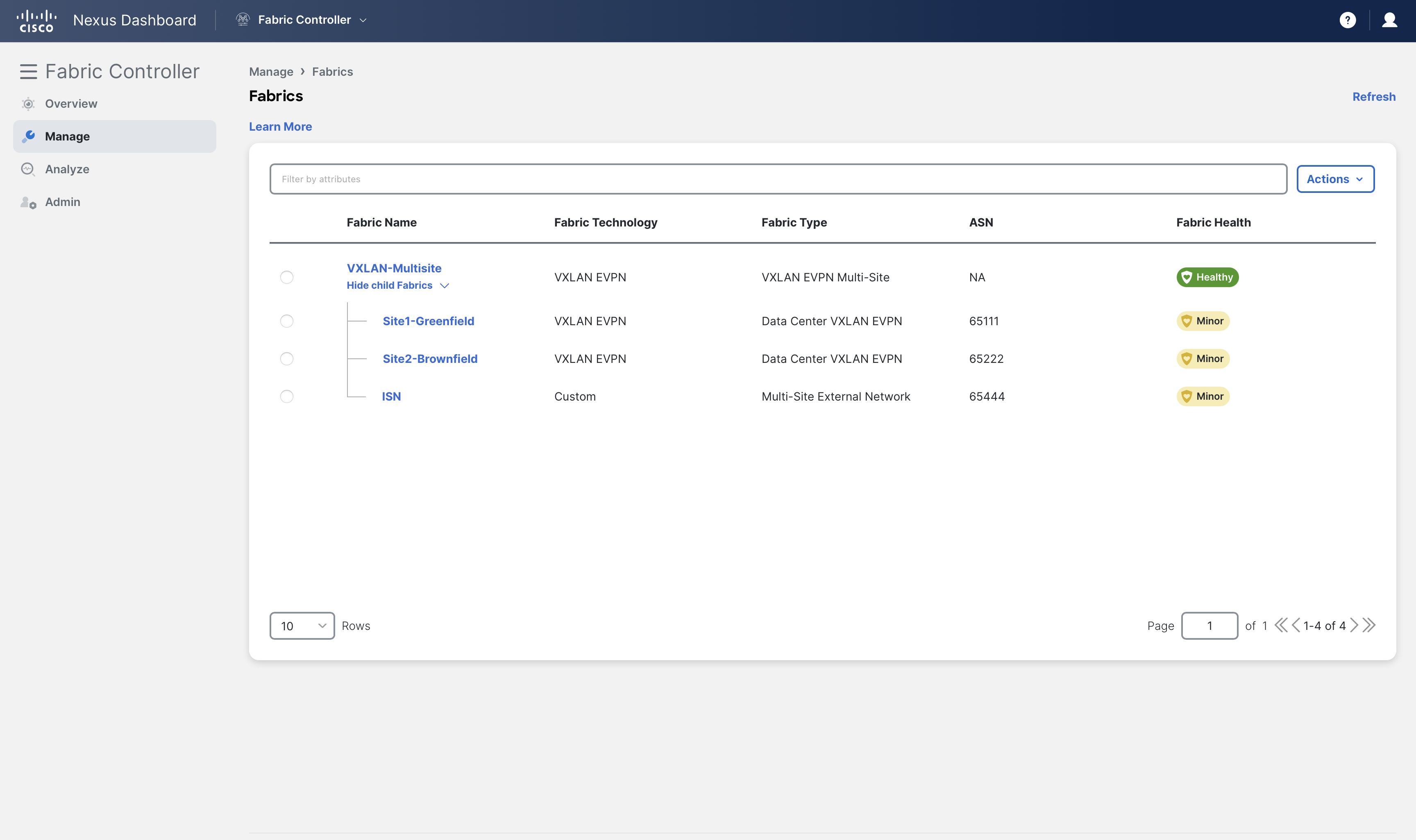
You should now have the following four fabrics
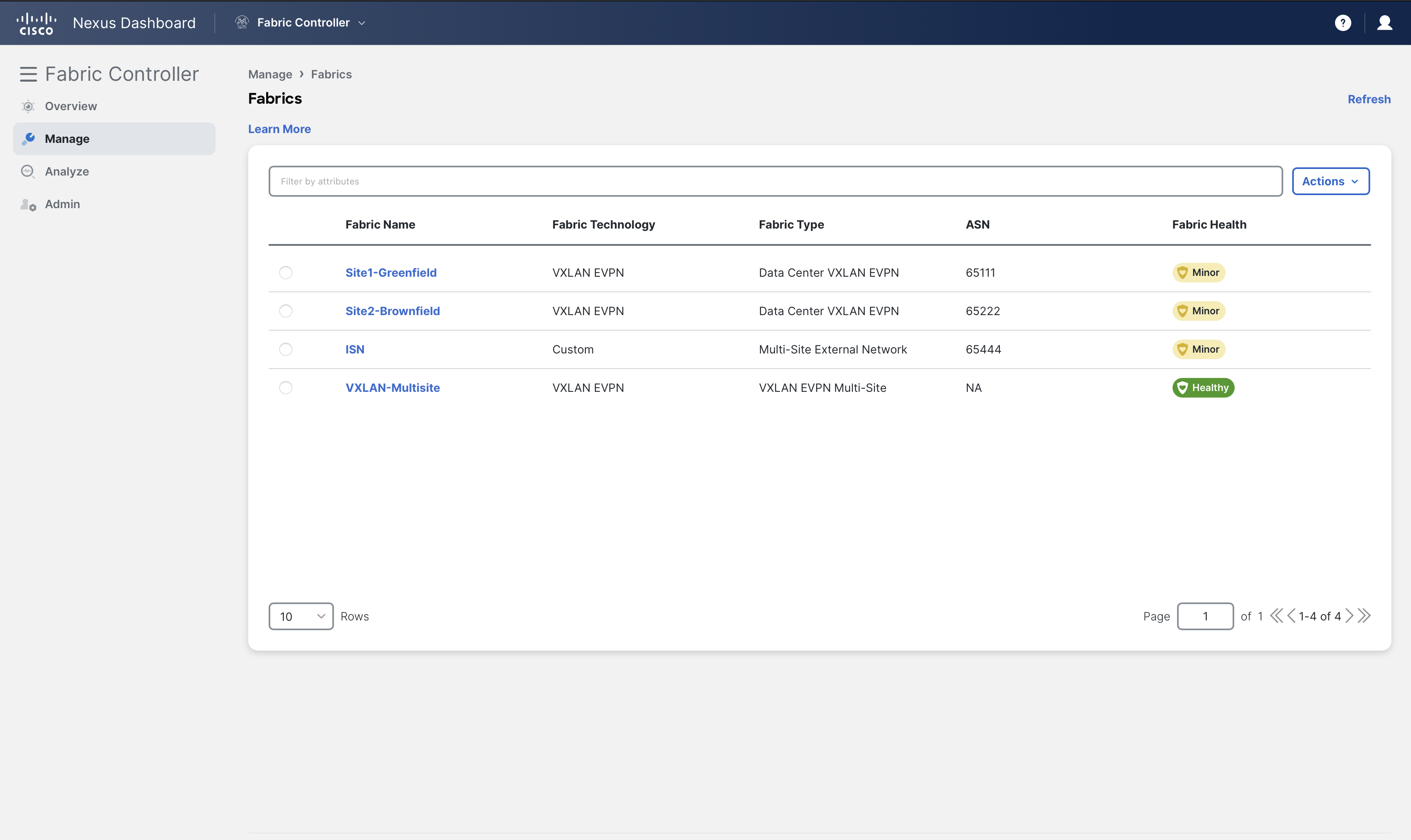
Add Fabrics to Multi-Site Domain
In the previous section, we created the VXLAN-Multisite MSD Fabric. Now we will add Child fabrics to it. A Child fabric can be an individual VXLAN fabric and/or an External fabric providing underlay/overlay reachability.
We have two VXLAN fabrics (Site1-Greenfield and Site2-Brownfield) and an External fabric ISN containing a Router-Server
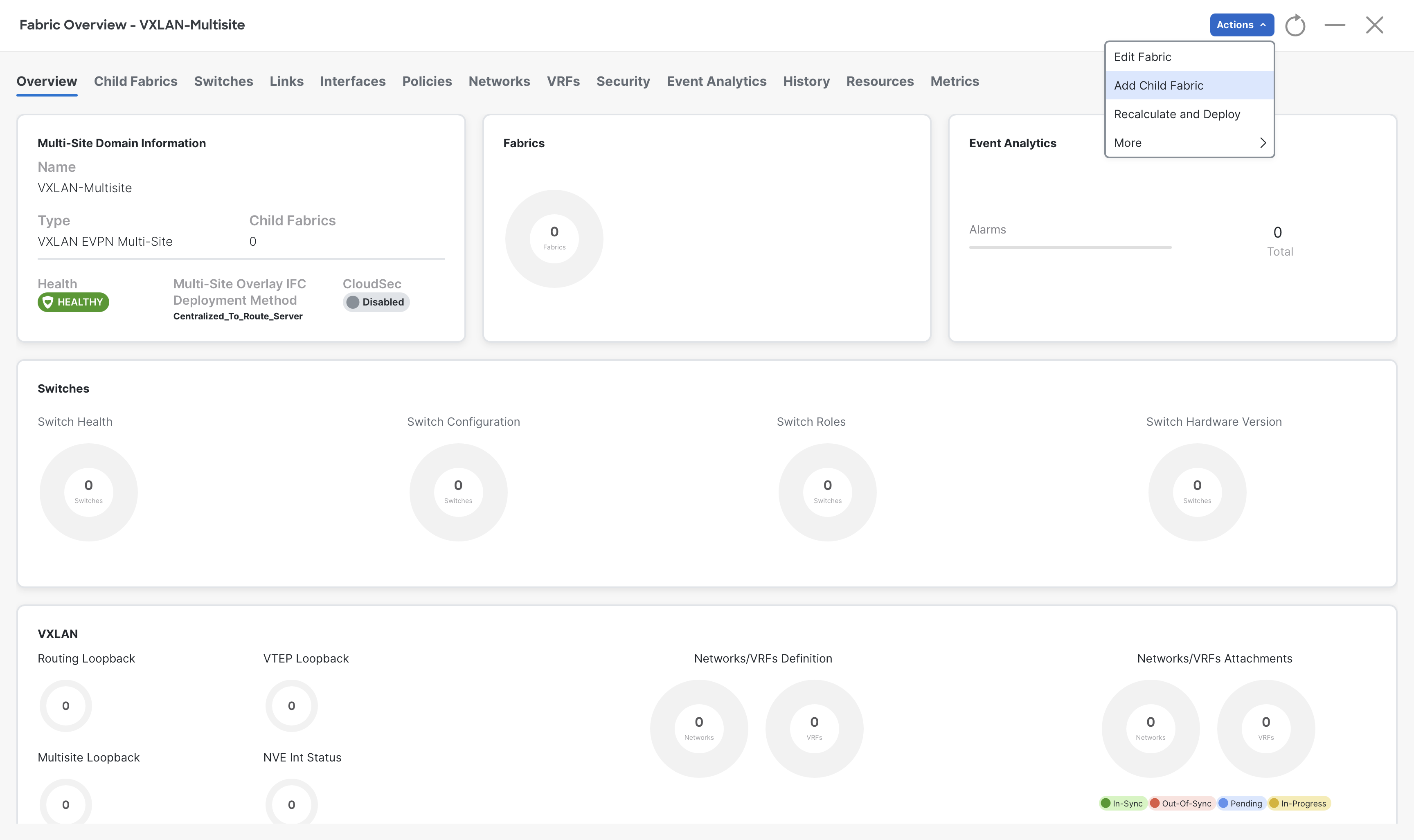
Step 1 – On Fabric Controller page, click on Manage > Fabrics then double-click on the VXLAN-Multisite fabric
Step 2 – On the Fabric Overview page, click Actions > Add Child Fabrics
Step 3 – Choose Site1-Greenfield fabric from the Select Child Fabrics dialog and then click Select
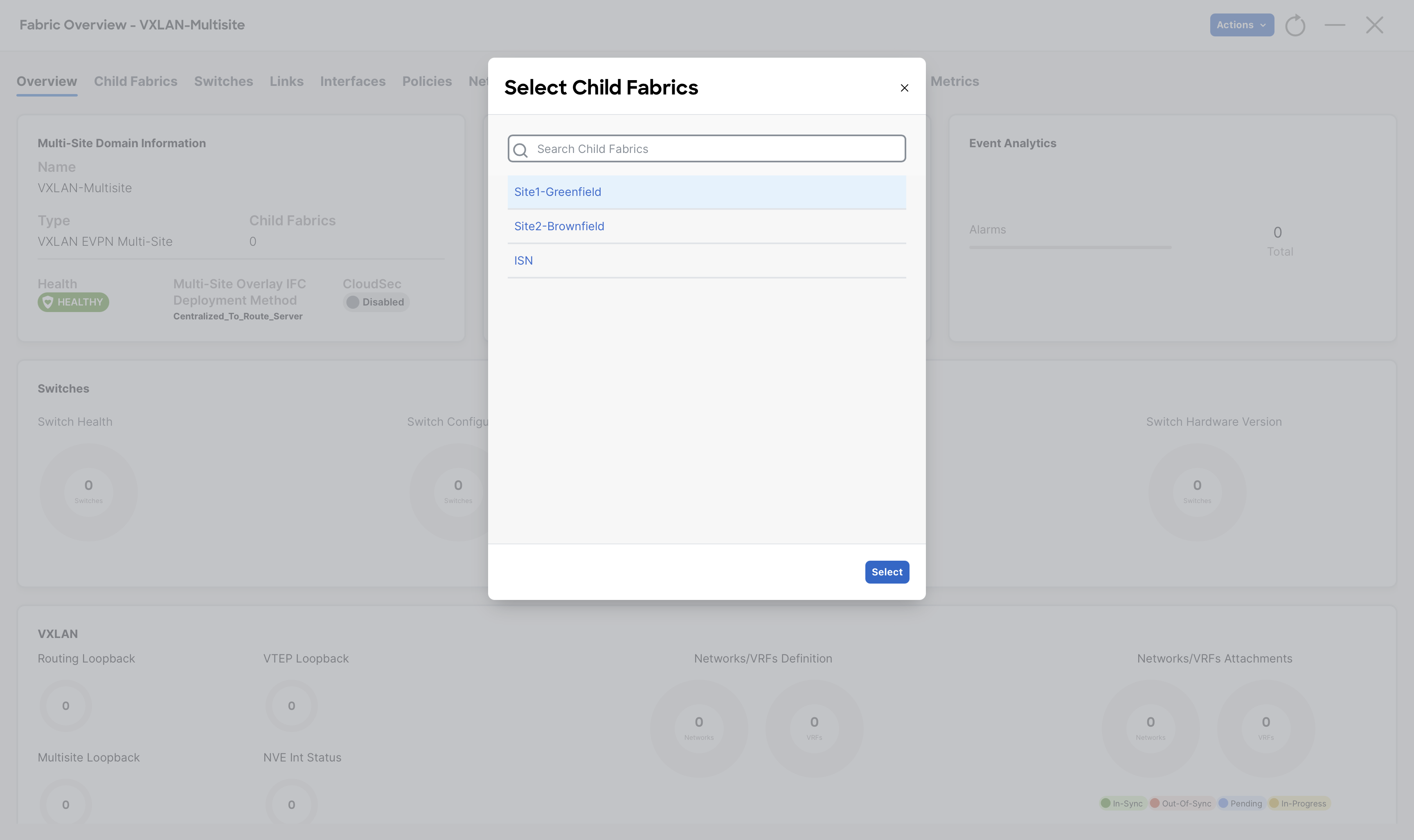
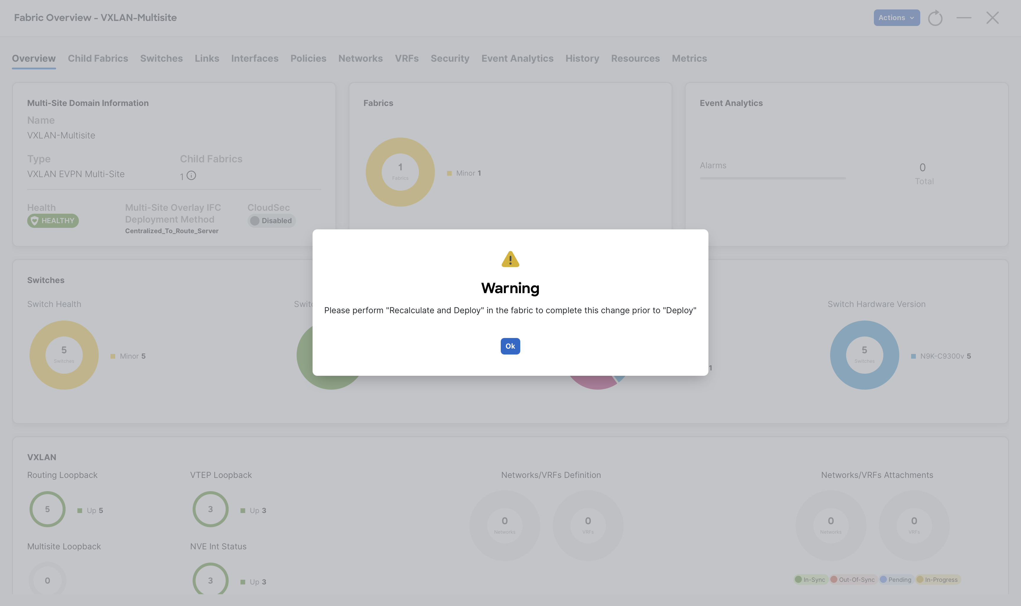
Step 4 - Click Ok on the Warning dialog box
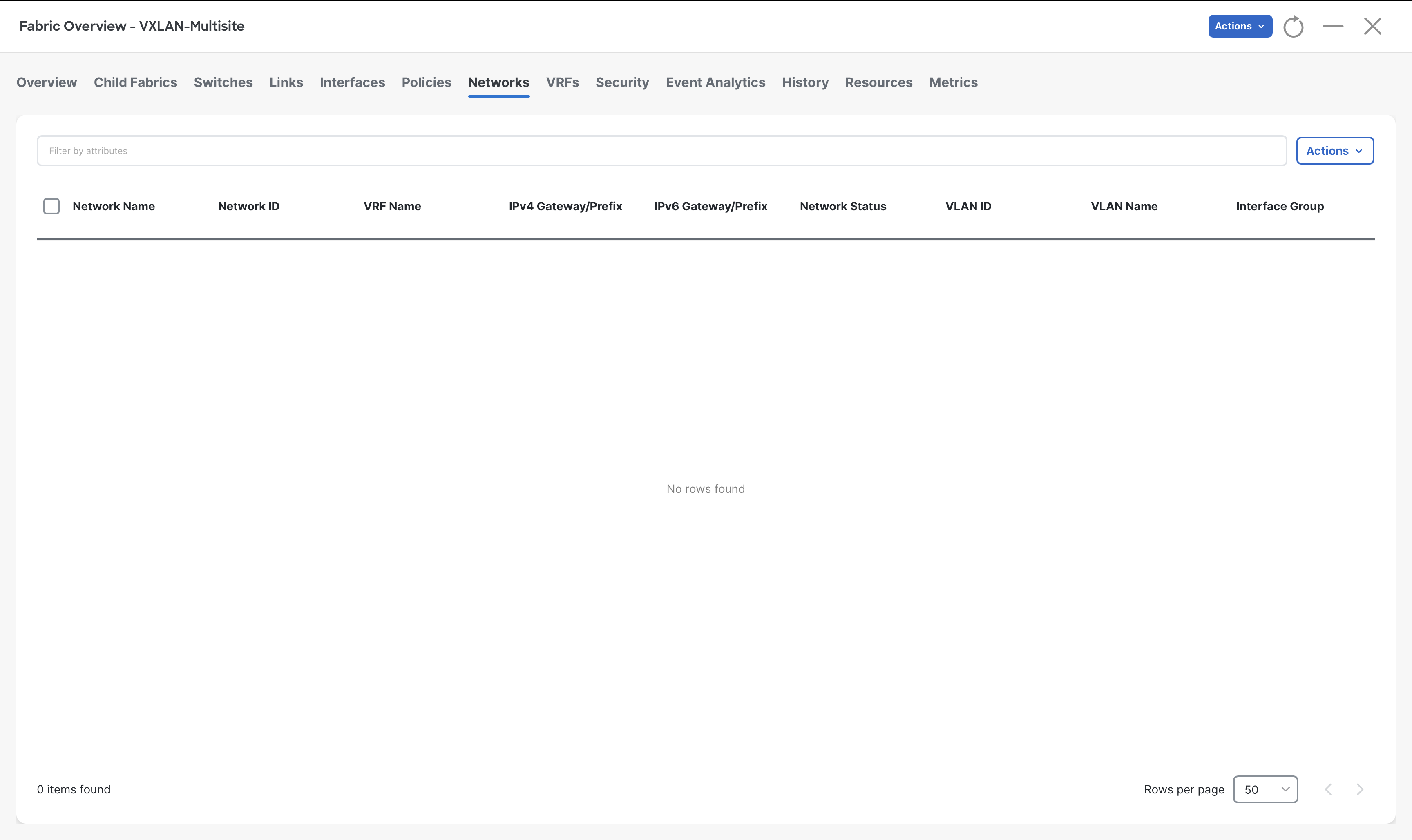
Step 5 – Verify the VRFs and Networks section, it should be empty as Site-1-Greenfield did not contain any of them
Step 6 - Similarly add Site2-Brownfield (by repeating steps 2 to 4) to the VXLAN-Multisite
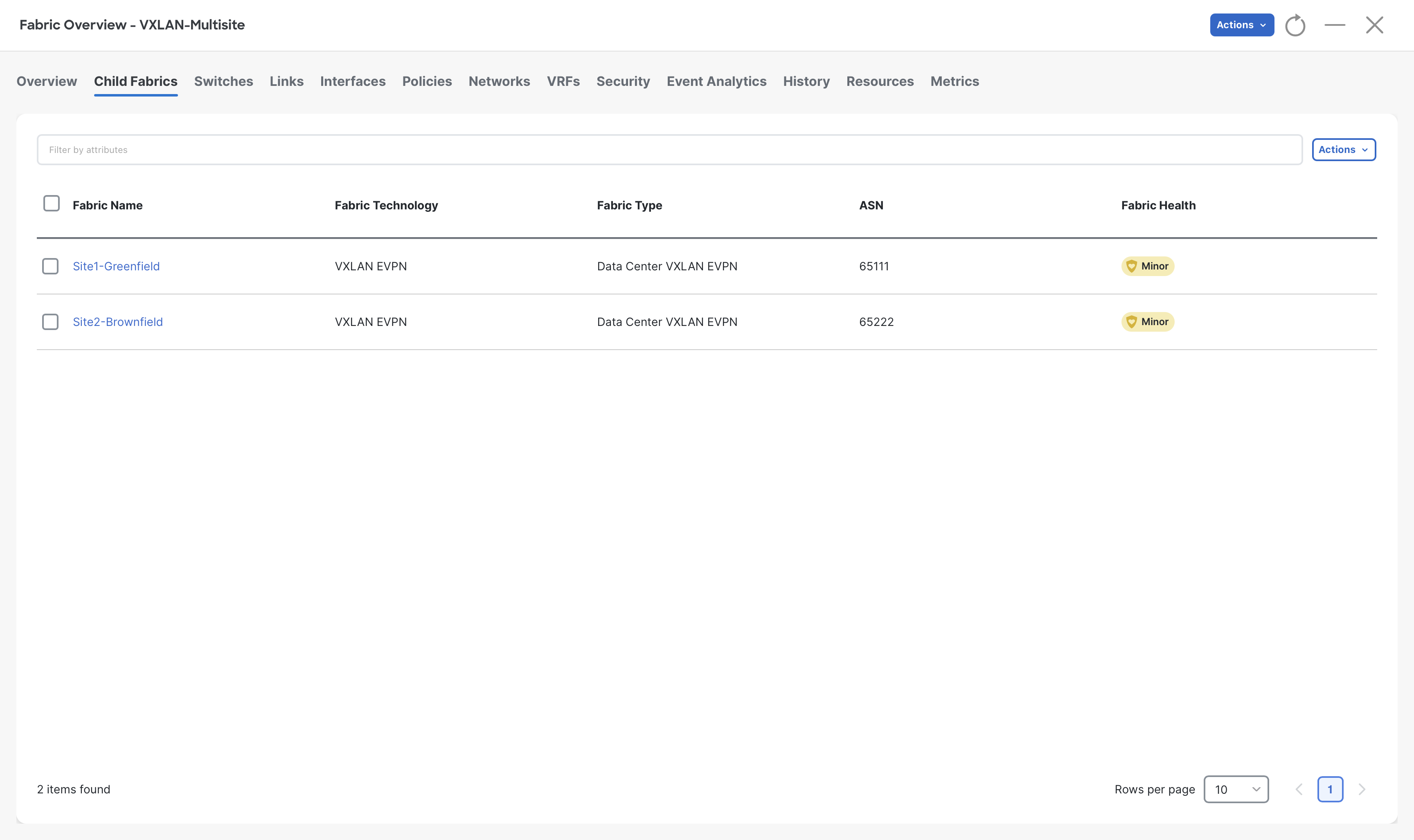
Step 7 – Now check again the VRFs and Networks, you should see the one that was part of the Site2-Brownfield
This demonstrates that VRFs and networks from children fabrics are imported into the Multi-Site parent fabric and then can be stretched everywhere.
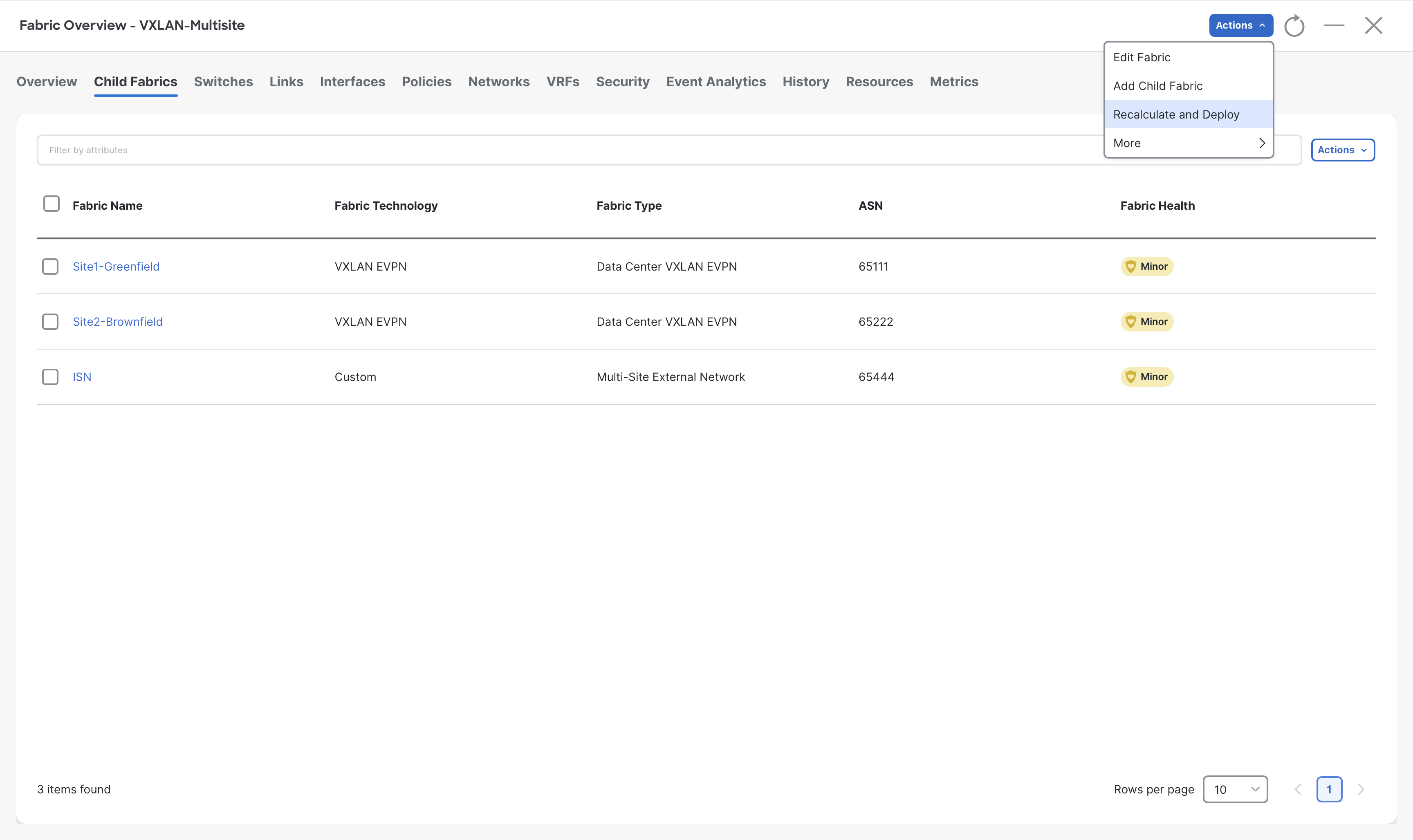
Step 8 – Similarly add the ISN fabric (by repeating steps 2 to 4) to the VXLAN-Multisite MSD fabric
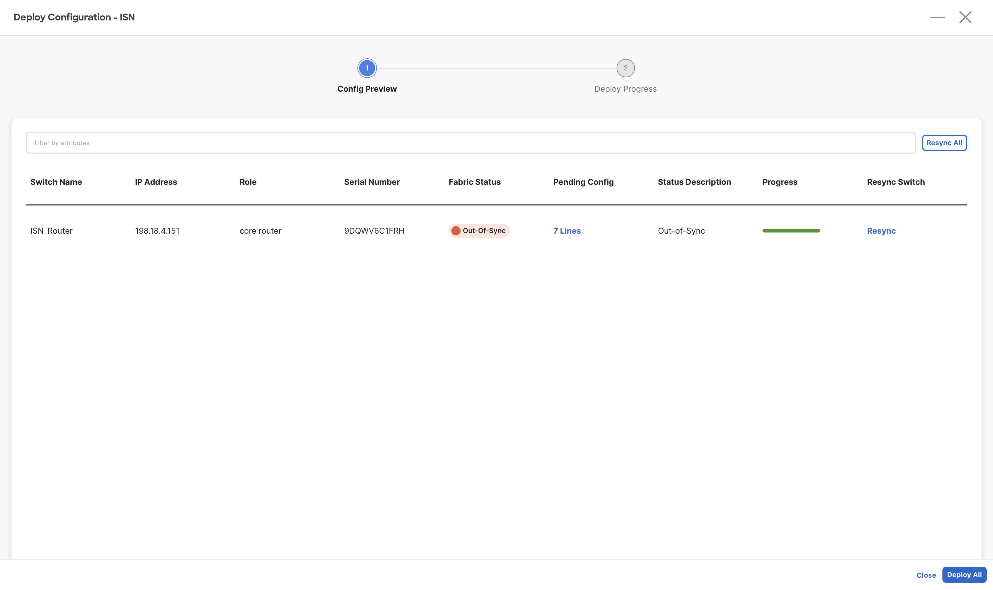
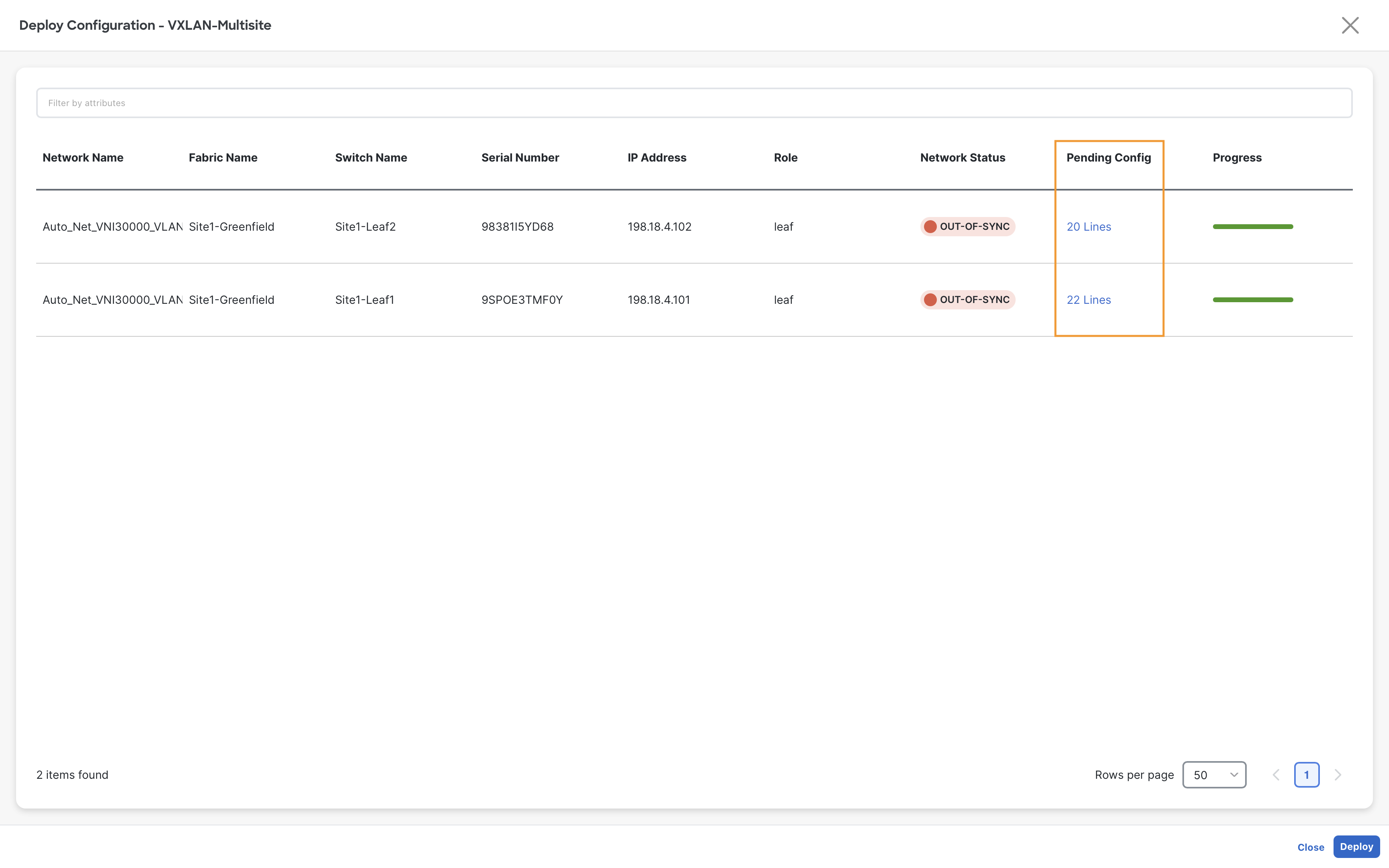
Step 9 – Once all three fabrics are added to the MSD, click on Actions > Recalculate and Deploy
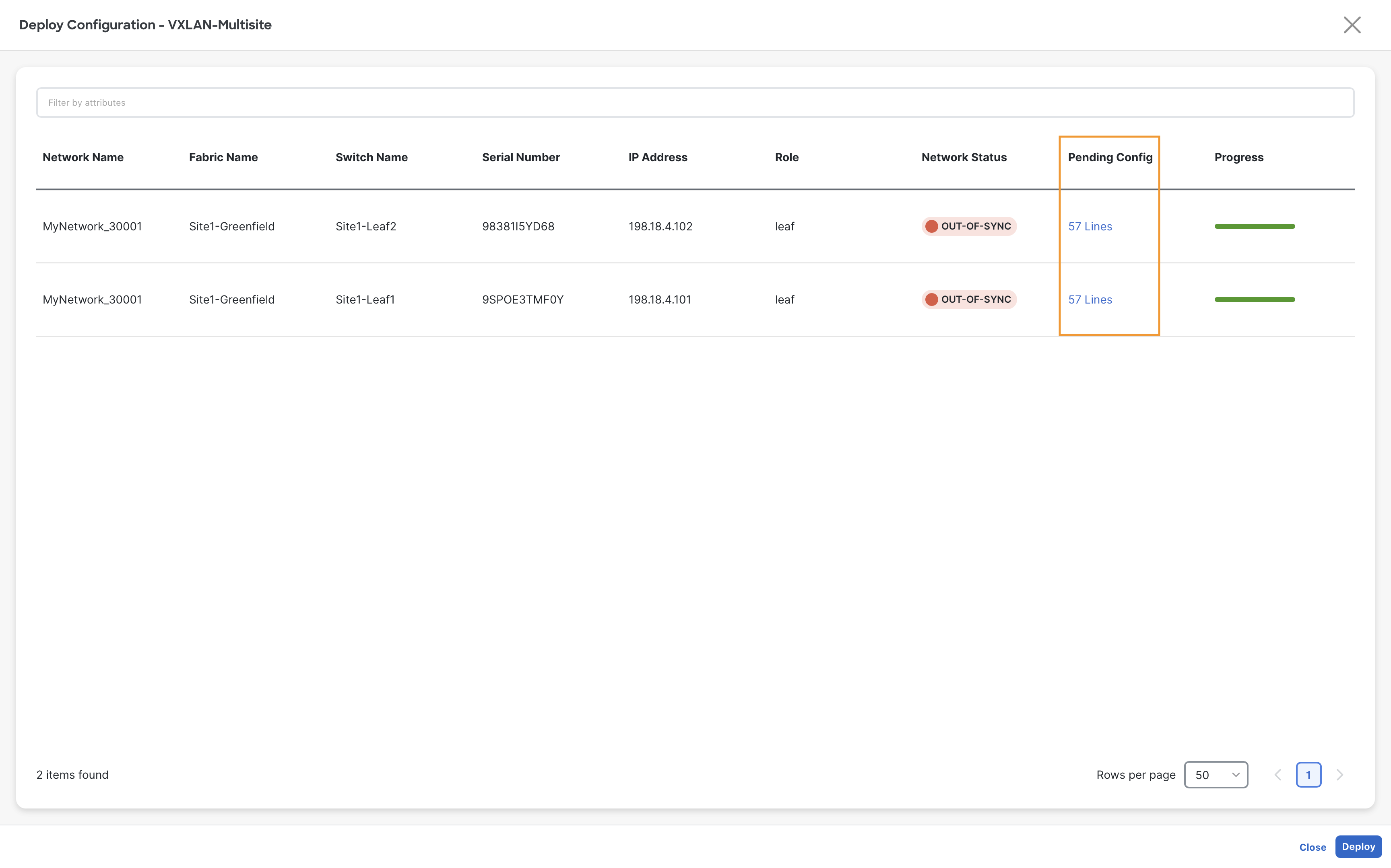
Step 10 – In the Deploy Configuration window, click the link in the Pending Config column to preview the configuration
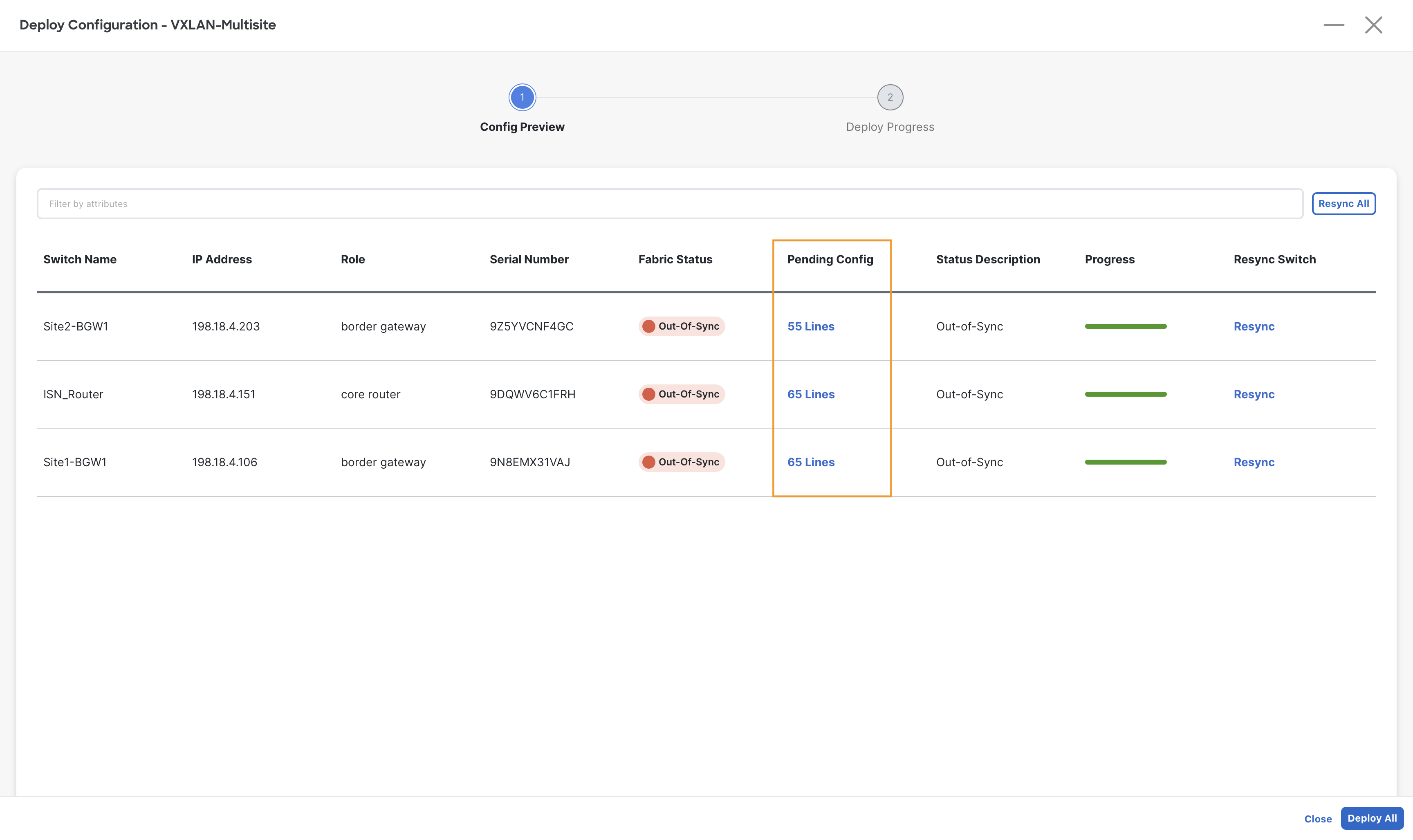
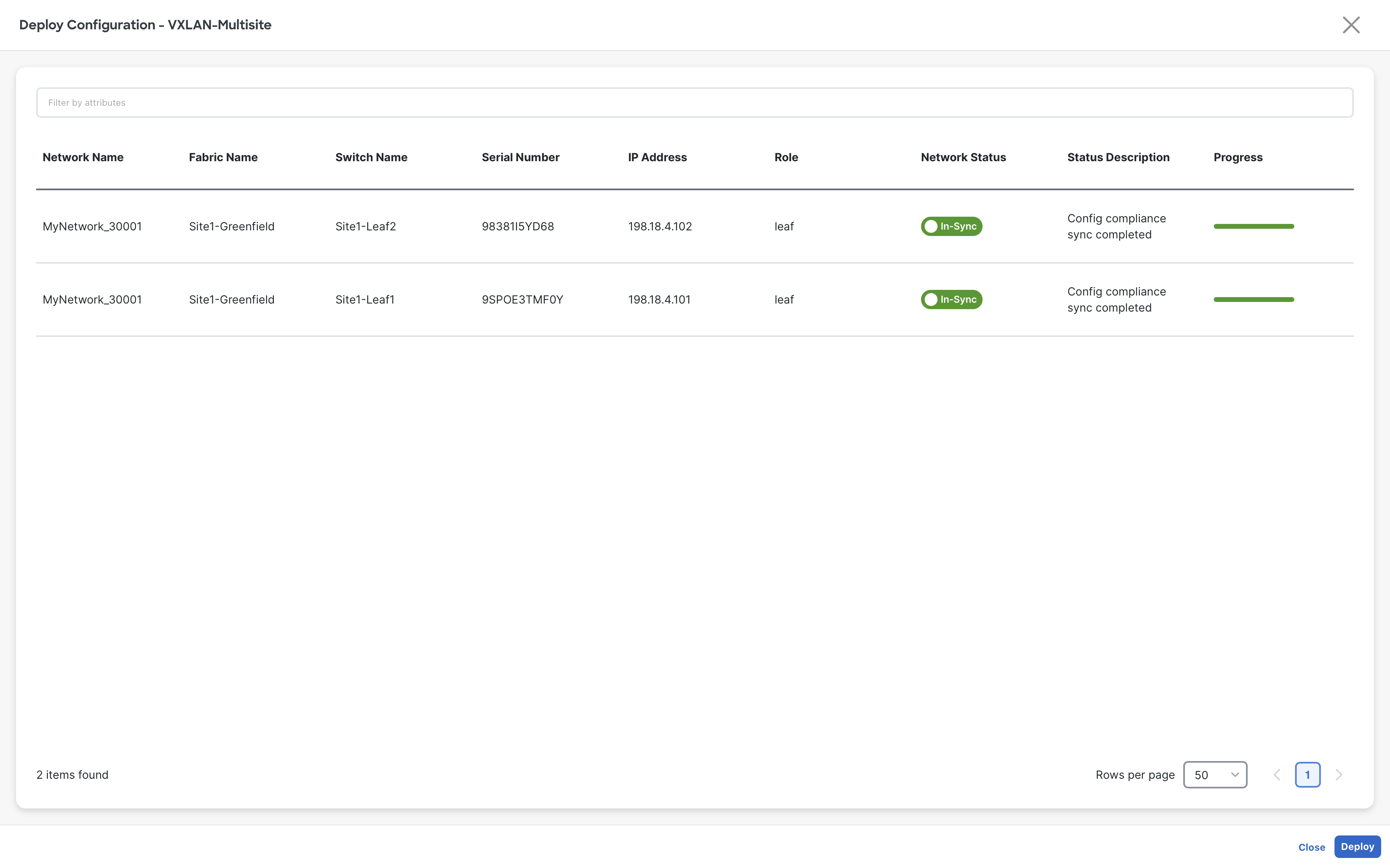
Step 11 - Click Deploy All and then, when the status changes to SUCCESS, click Close
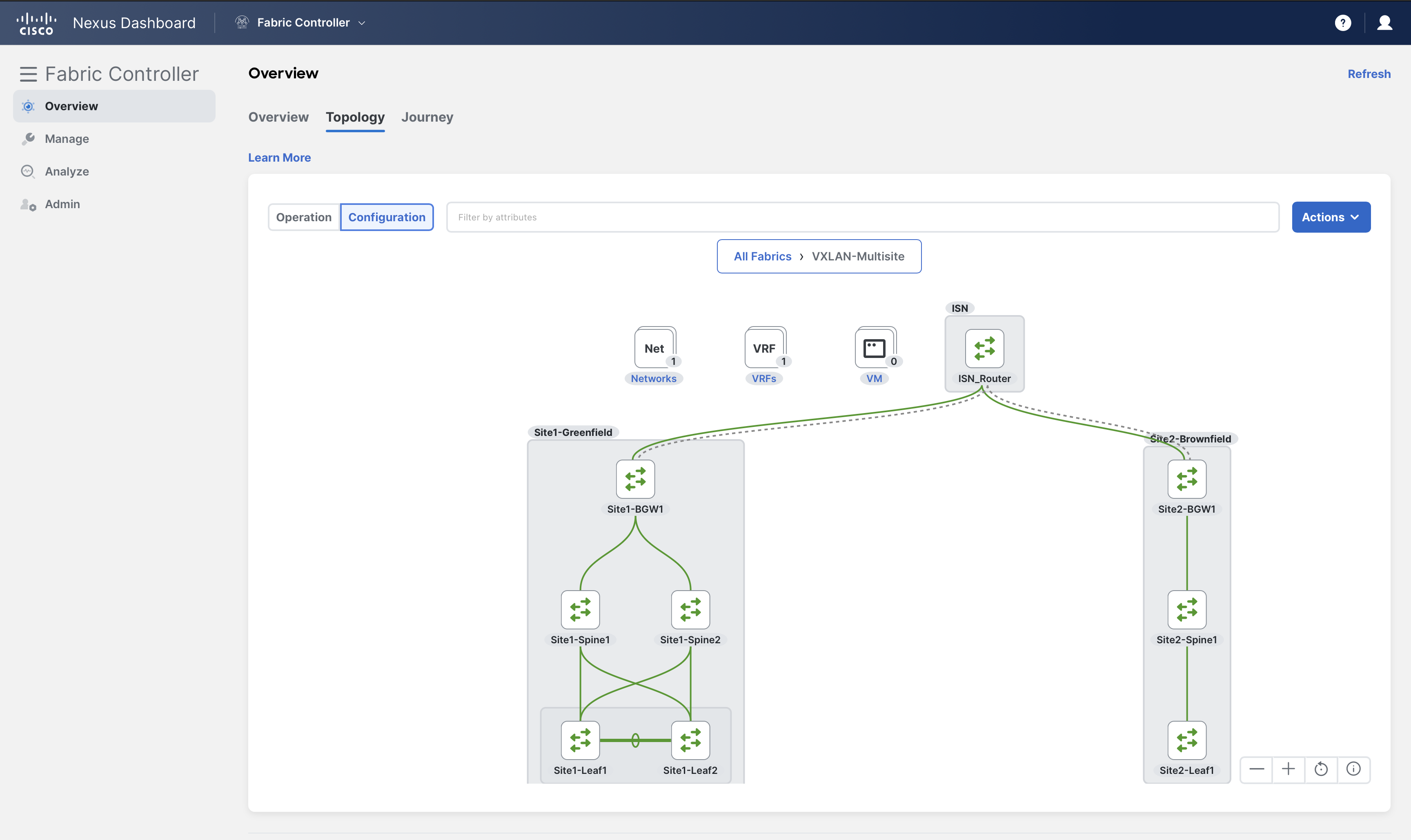
Step 12– On Fabric Controller page, click Overview and go to Topology to verify the Vxlan-Multisite fabric in topology view
You will notice all three fabrics are grouped together under the Vxlan-Multisite MSD fabric
You can double click on the darker gray area to render the detailed view
(Optional) From the Action settings you can enter in edit mode and move nodes and fabrics around to customize the topology.
Fabric groupings can also be verified under Manage > Fabrics
Verification of MSD (Optional)
Log into the ISN_Router using MPutty (admin/C1sco12345) and verify BGP peering for IPv4 and L2VPN EVPN address families using the following commands:
ISN_Router
show bgp ipv4 unicast summary
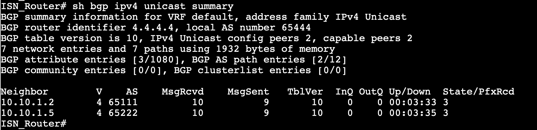
Info
We use ipv4 unicast to announce the BGWs loopbacks in the ISN network, serving as the underlay.
ISN_Router
show bgp l2vpn evpn summary
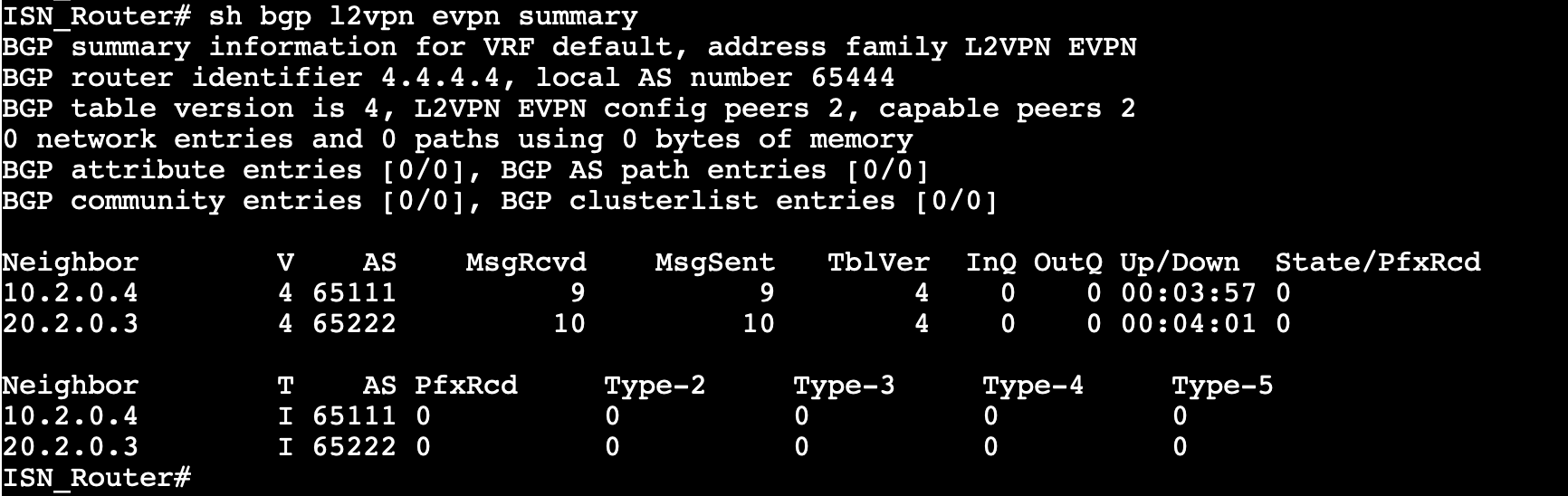
Info
We use EVPN to propagate the reachability for the end hosts and external subnets in each site.
Deploy VRFs/Networks
The following table summarizes the IP details and connectivity for the Servers:
| Server | IP Address | Switch | Port |
|---|---|---|---|
| Server1 | 192.168.11.101/24 | Site1-Leaf1 | Eth1/5 |
| Server2 | 192.168.12.101/24 | Site1-Leaf1 & Site1-Leaf2 | vPC1 (Eth1/6 on both switches) |
| Server3 | 192.168.11.102/24 | Site2-Leaf | Eth1/5 |
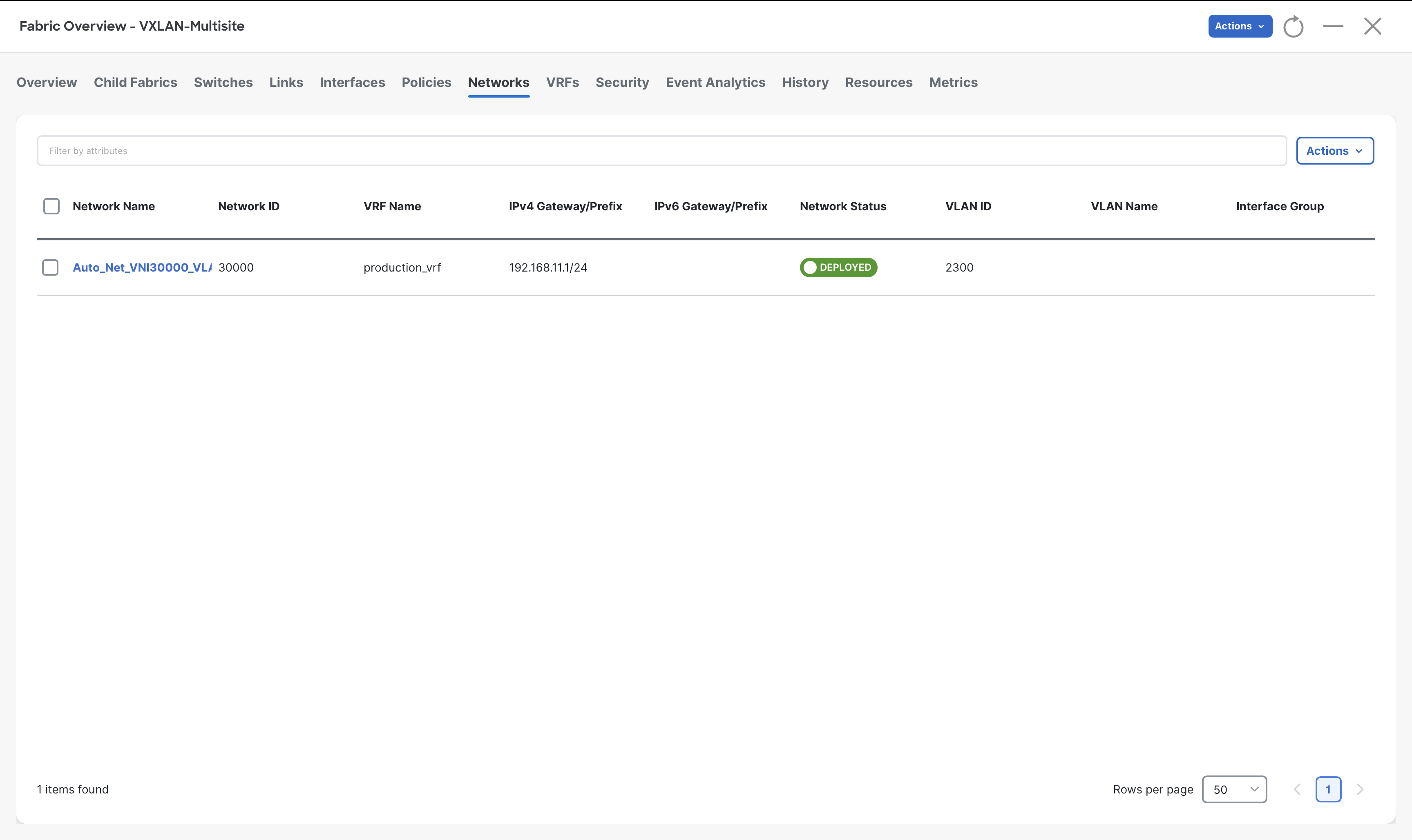
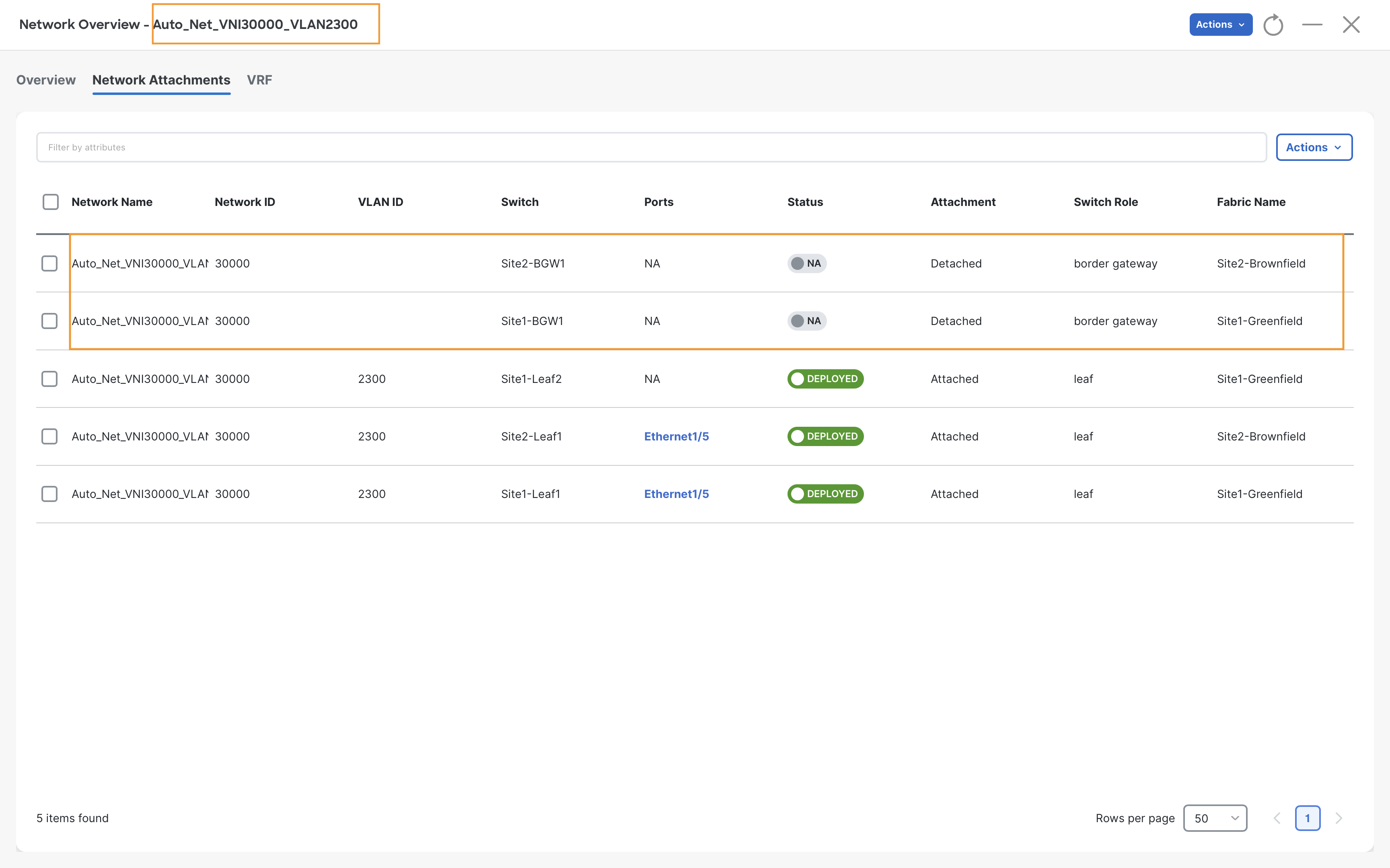
Server1 and Server3 are single-attached and are part of the same network Auto_Net_VNI30000_VLAN2300 (192.168.11.1/24), which has been imported to MSD from the Site2-Brownfield fabric.
For Server2, let's create a new network using the following steps:
Step 1 - On Fabric Controller page, click Manage > Fabrics and then double-click on the VXLAN-Multisite fabric
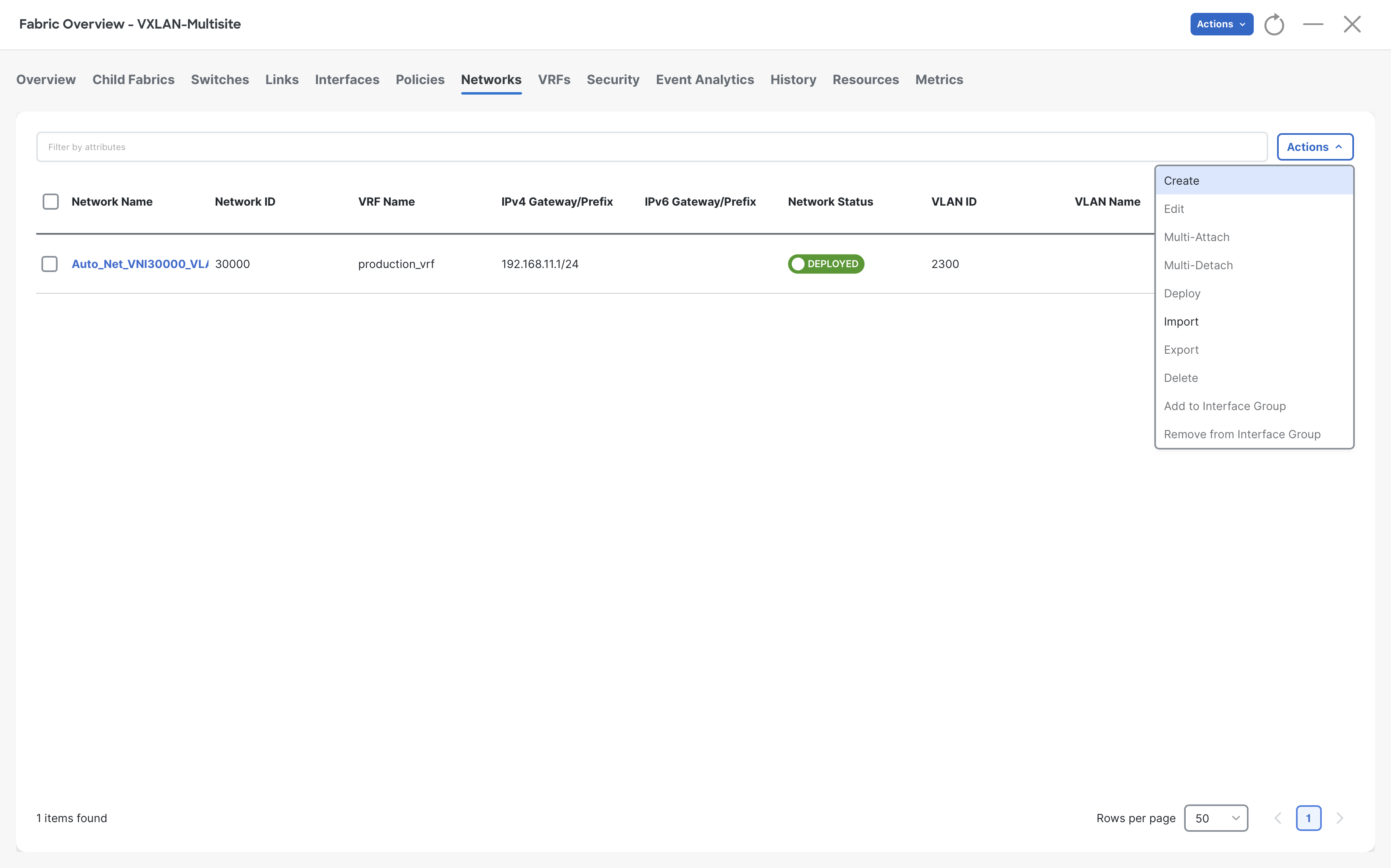
Step 2 – On the Fabric Overview page, click on the Networks tab
Step 3 – Click Actions > Create
Step 4 – On the Create Network page, complete the following steps:
- NDFC automatically populates the Network Name, VRF Name, and Network ID
- Click on the Propose VLAN button for NDFC to allocate a VLAN from the allocated pool
- In the IPv4 Gateway/NetMask field, type 192.168.12.1/24
- Click on Create
| Parameter | Value/Setting |
|---|---|
| Network Name | MyNetwork_30001 |
| VRF Name | production_vrf |
| Network ID | 30001 |
| VLAN ID | 2301 |
| IPv4 Gateway/NetMask | 192.168.12.1/24 |
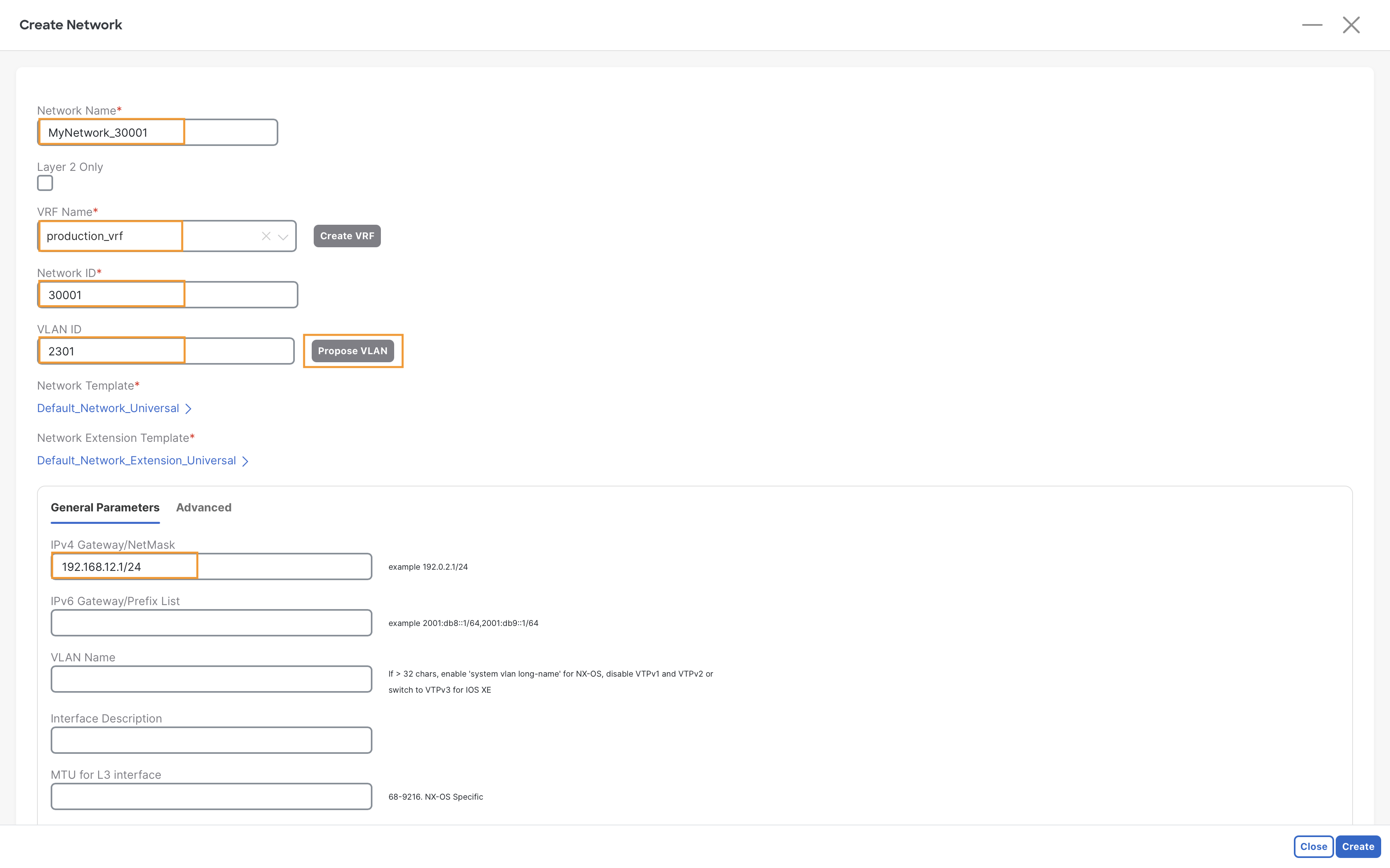
Step 5 – Click Create on the Create Network page
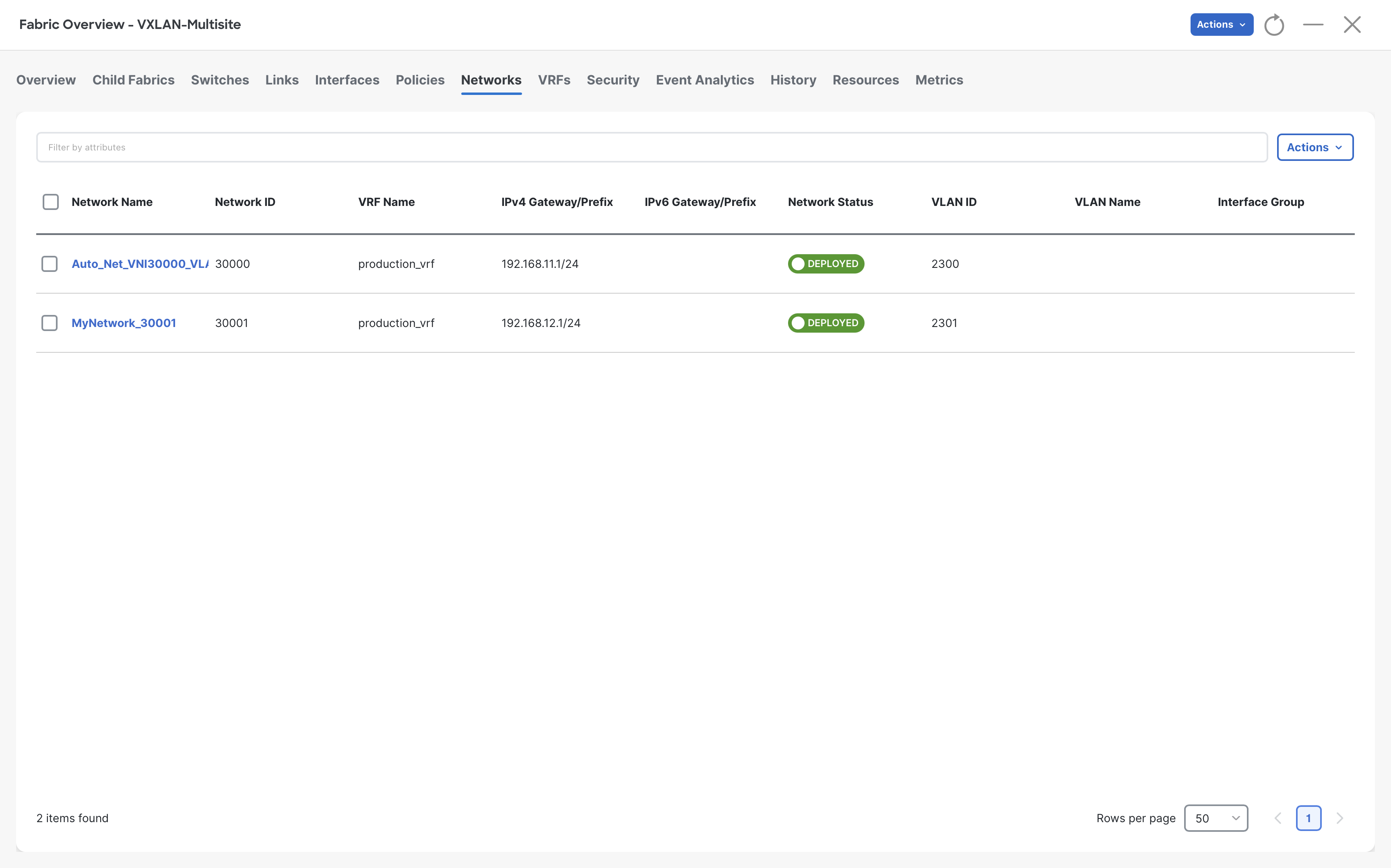
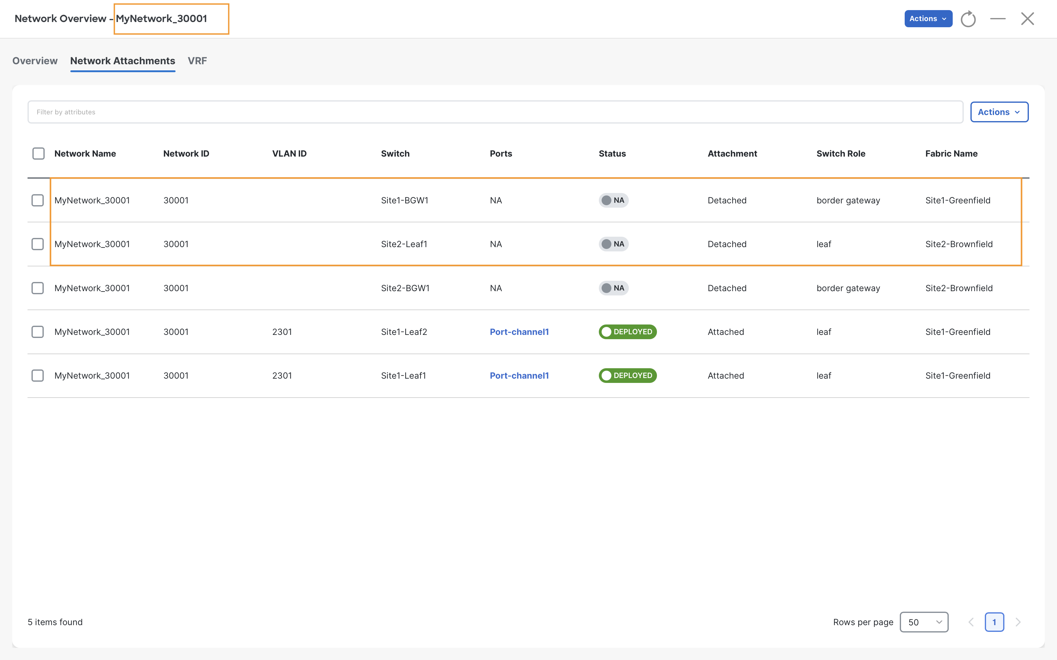
Step 6 – We now have a new network, MyNetwork_30001 created
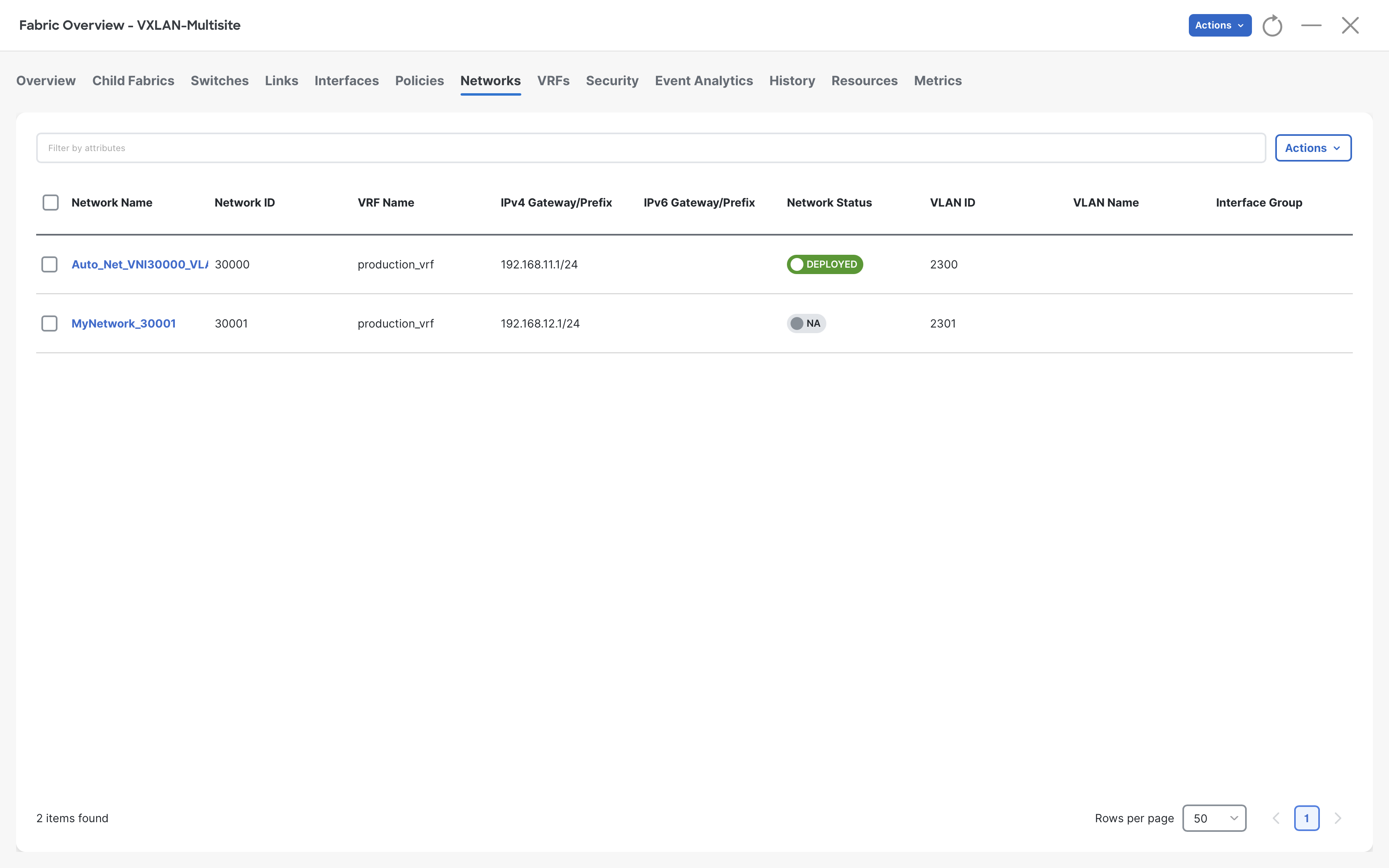
Notice that the network MyNetwork_30001 has not yet been attached to any switches. Therefore, under network status, we see NA, while the other network is in the deployed status.
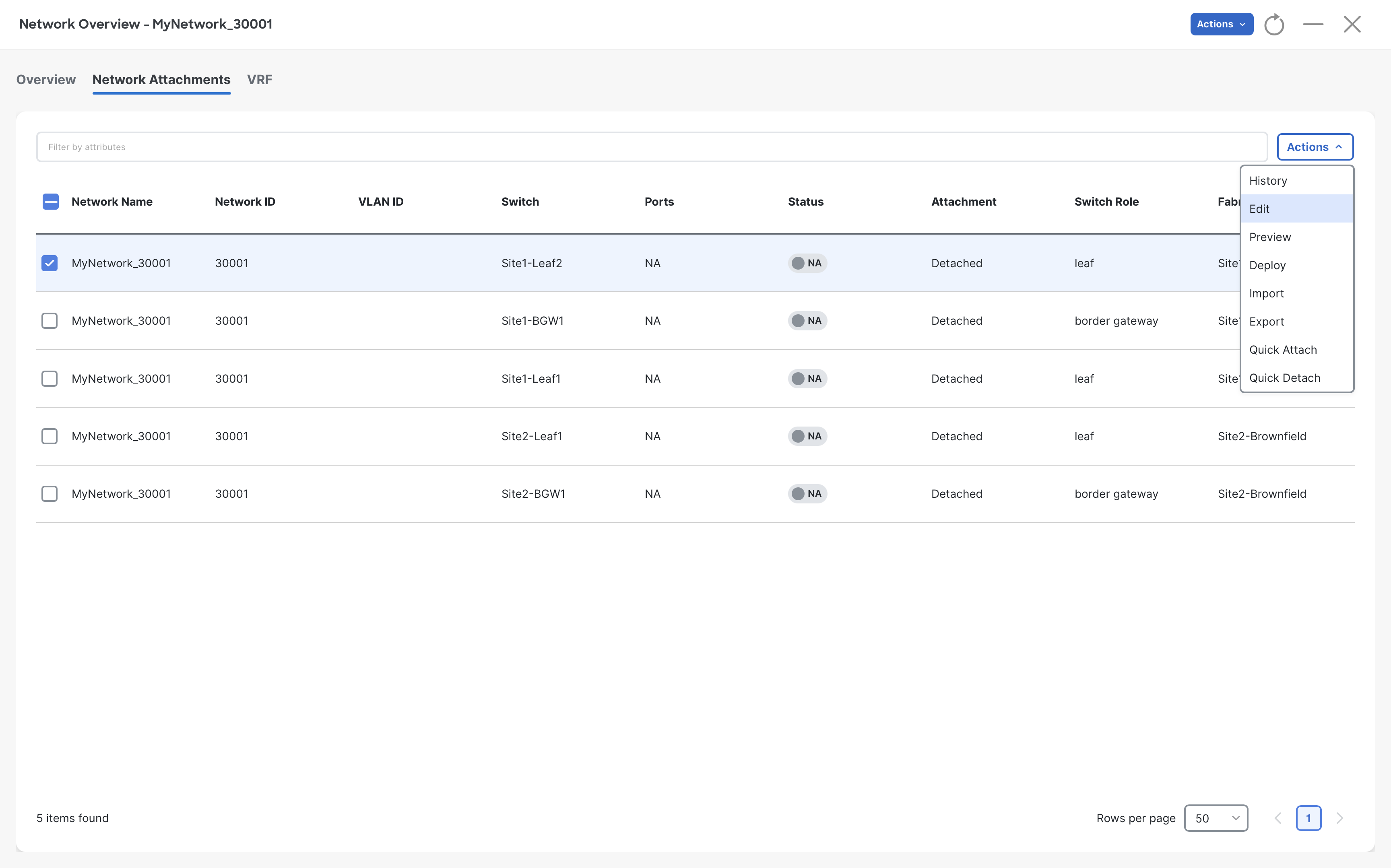
Step 7 – To attach the network MyNetwork_30001, we go to the Network Overview page for this network by double-clicking on it
Now, move to Network Attachments tab, select either Site1-Leaf1 or Site1-Leaf2, and click Actions > Edit
Tip
You can select either Site1-Leaf1 or Site1-Leaf2 as they are forming a vPC. Because of this, in the next steps, you will be able to see the interfaces of both leaves.
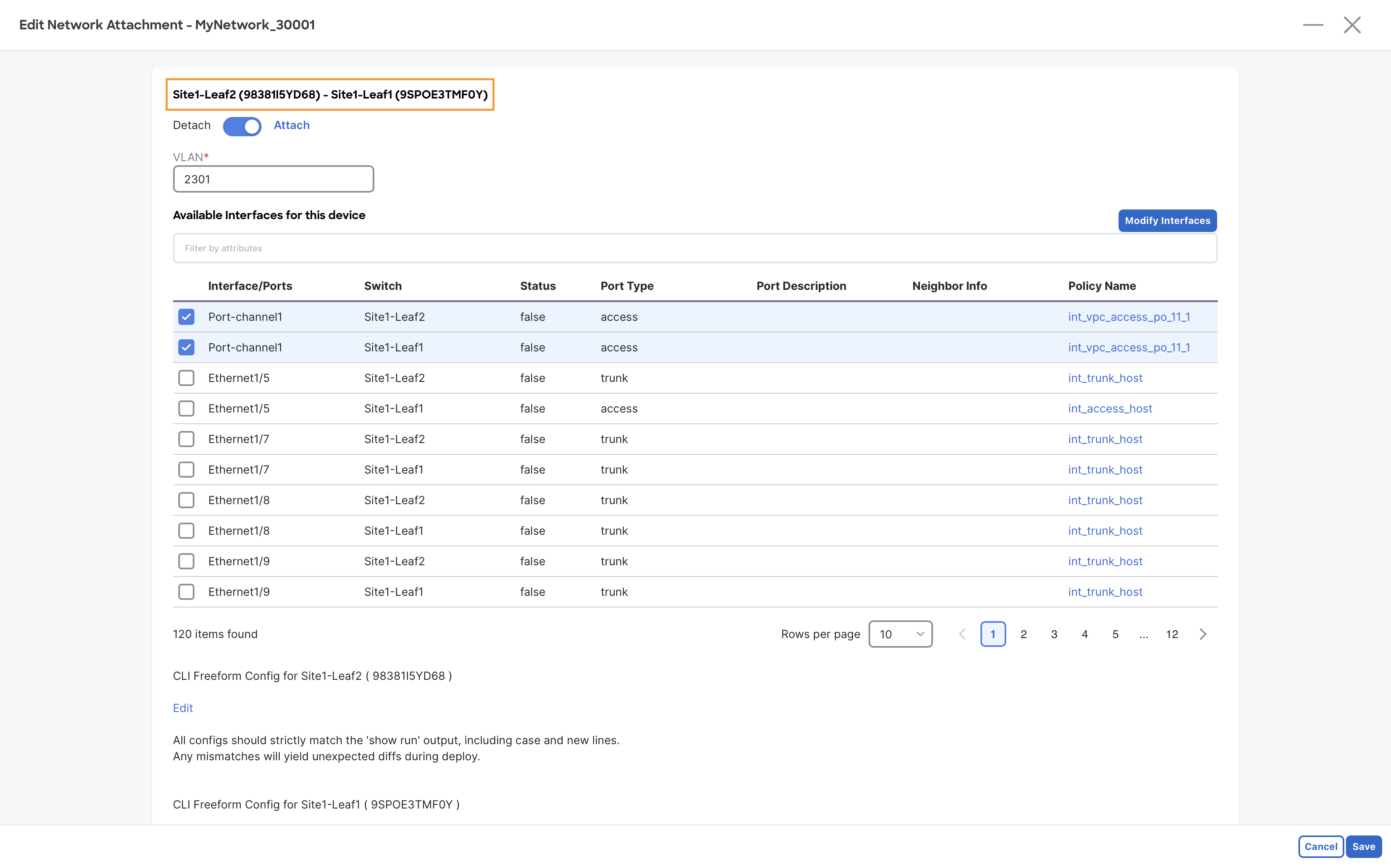
Step 8 – On the Edit Network Attachment page, move the slider to Attach and select the Port-channel1 (vPC1) from both Site1-Leaf1 & Site1-leaf2 switches by clicking on the checkboxes
Then click on Save
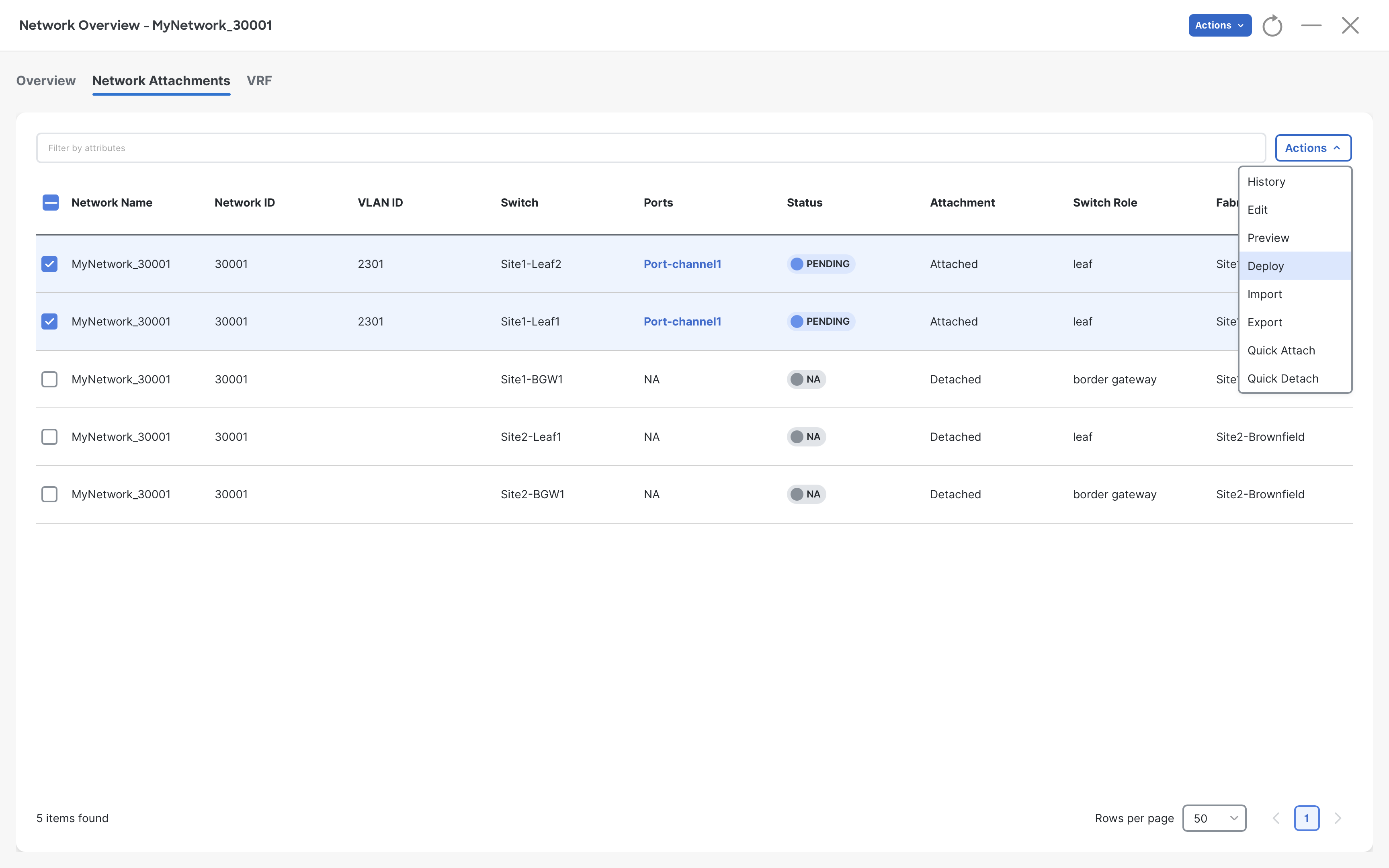
Step 9 – On the Network Overview page, select the Site1-Leaf1 & Site1-leaf2 switches and click Actions > Deploy
(Optional) You can preview the configuration by clicking Actions > Preview
Step 10 – On the Deploy Configuration page, click Deploy
Once the deployment is completed, close the deployment window.
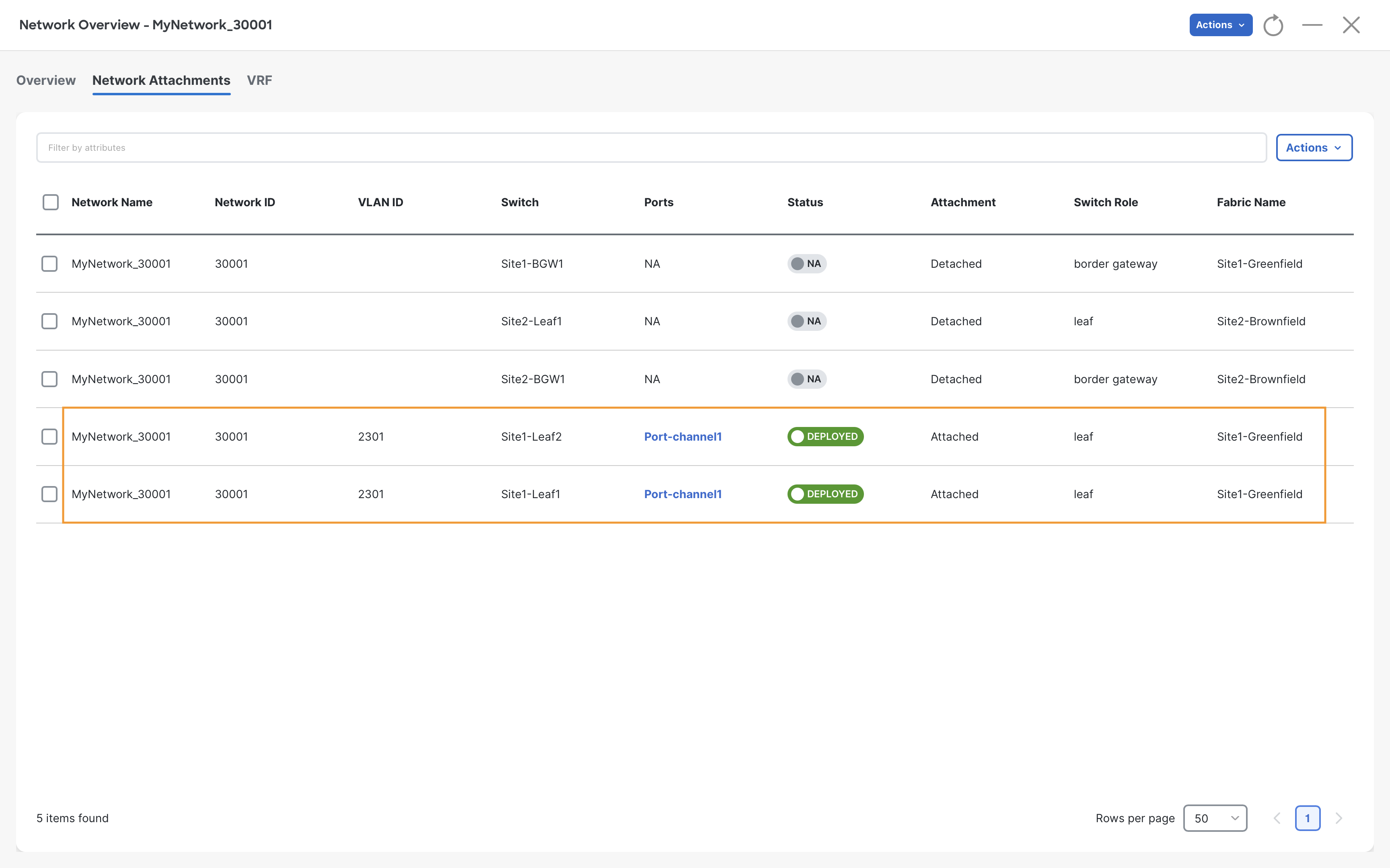
Step 11 – We now have the MyNetwork_30001 network in the deployed status
At this moment, we should have a successful ping to the Gateway IP (192.168.12.1)
Server2
ping 192.168.12.1
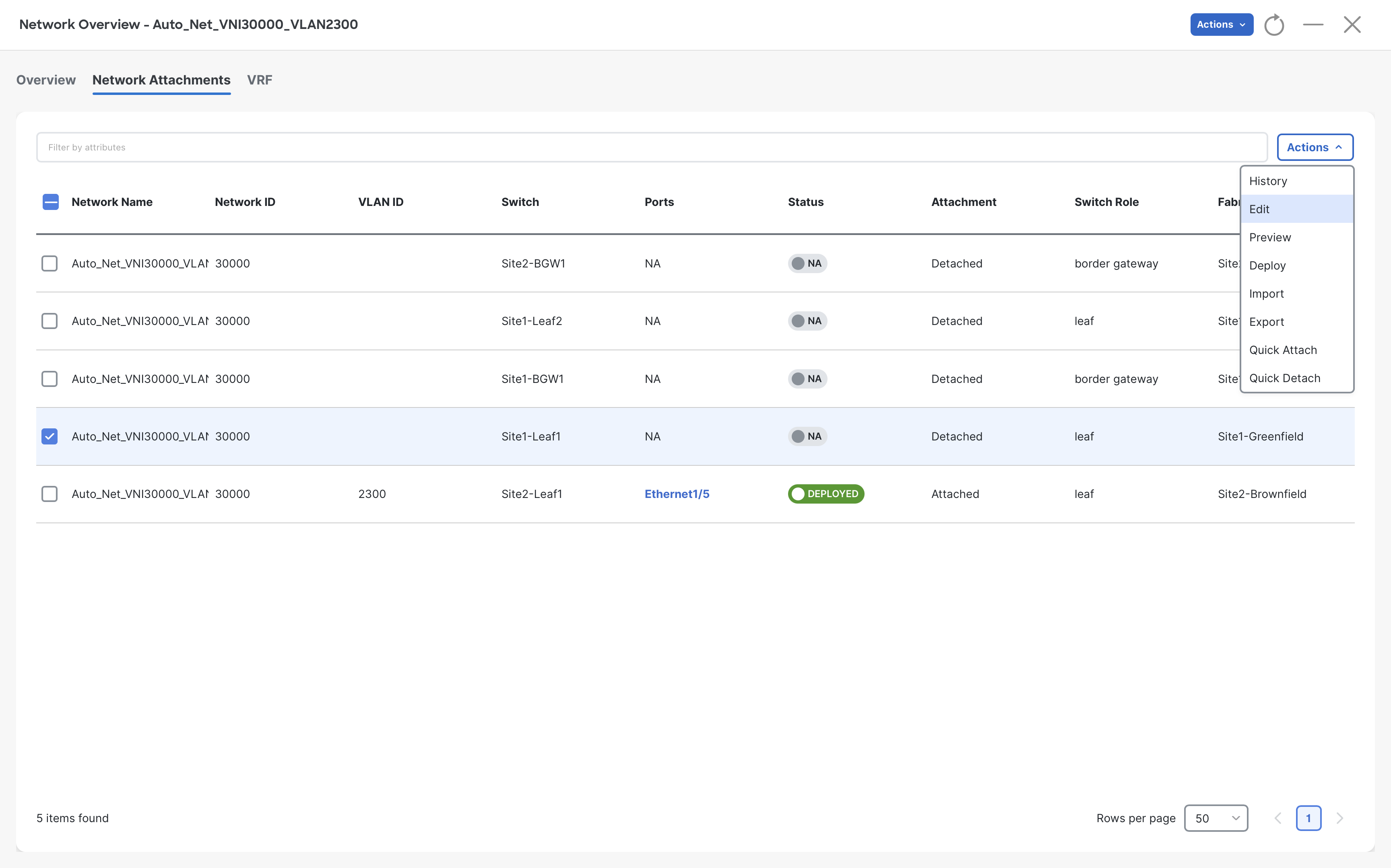
Similarly, we also need to deploy the Auto_Net_VNI30000_VLAN2300 network on Site1-Leaf1 orphan port Eth1/5
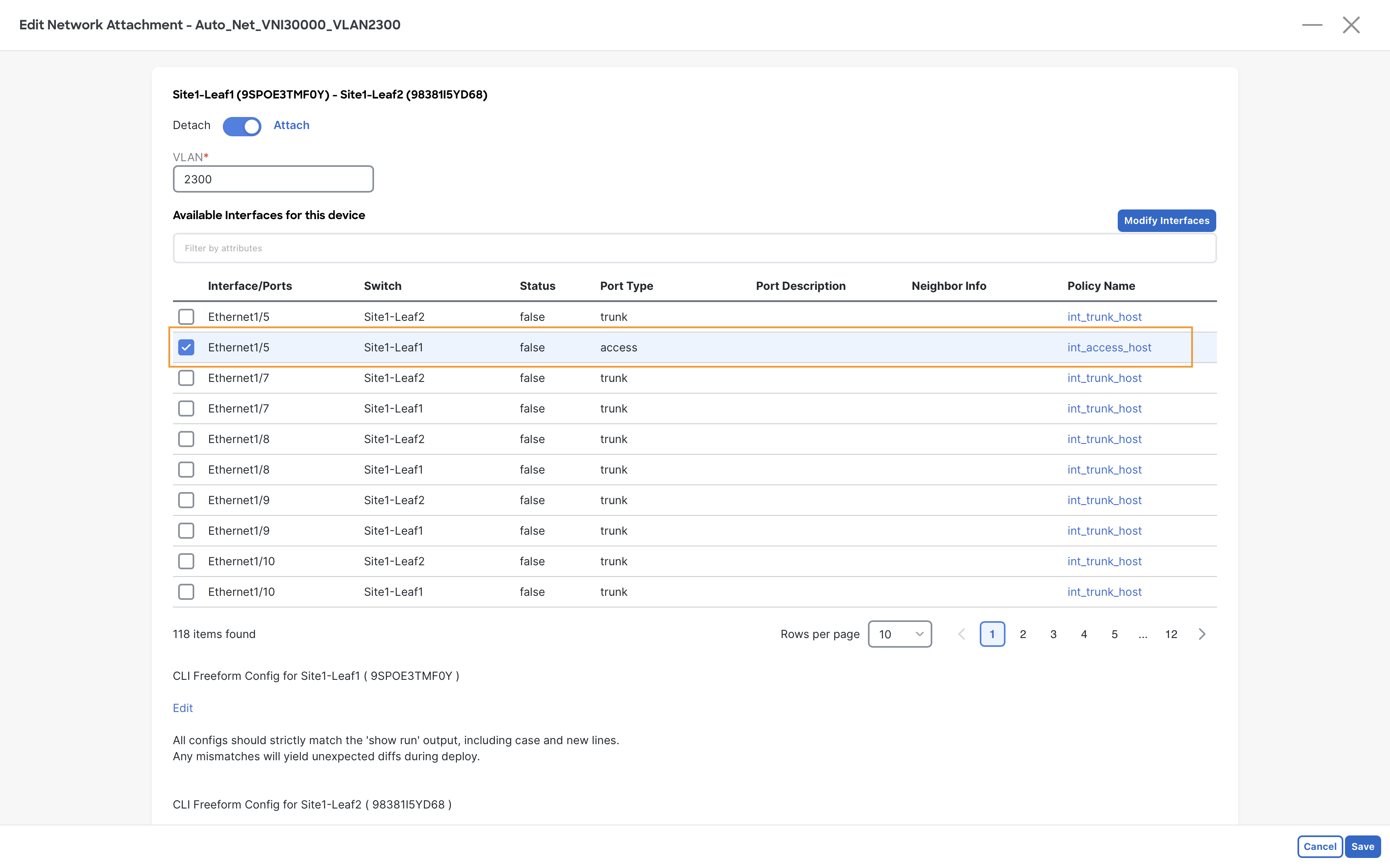
Step 12 – Repeat steps 6 to 9 to attach Auto_Net_VNI30000_VLAN2300 network to the Eth1/5 interface of the Site1-Leaf1 switch
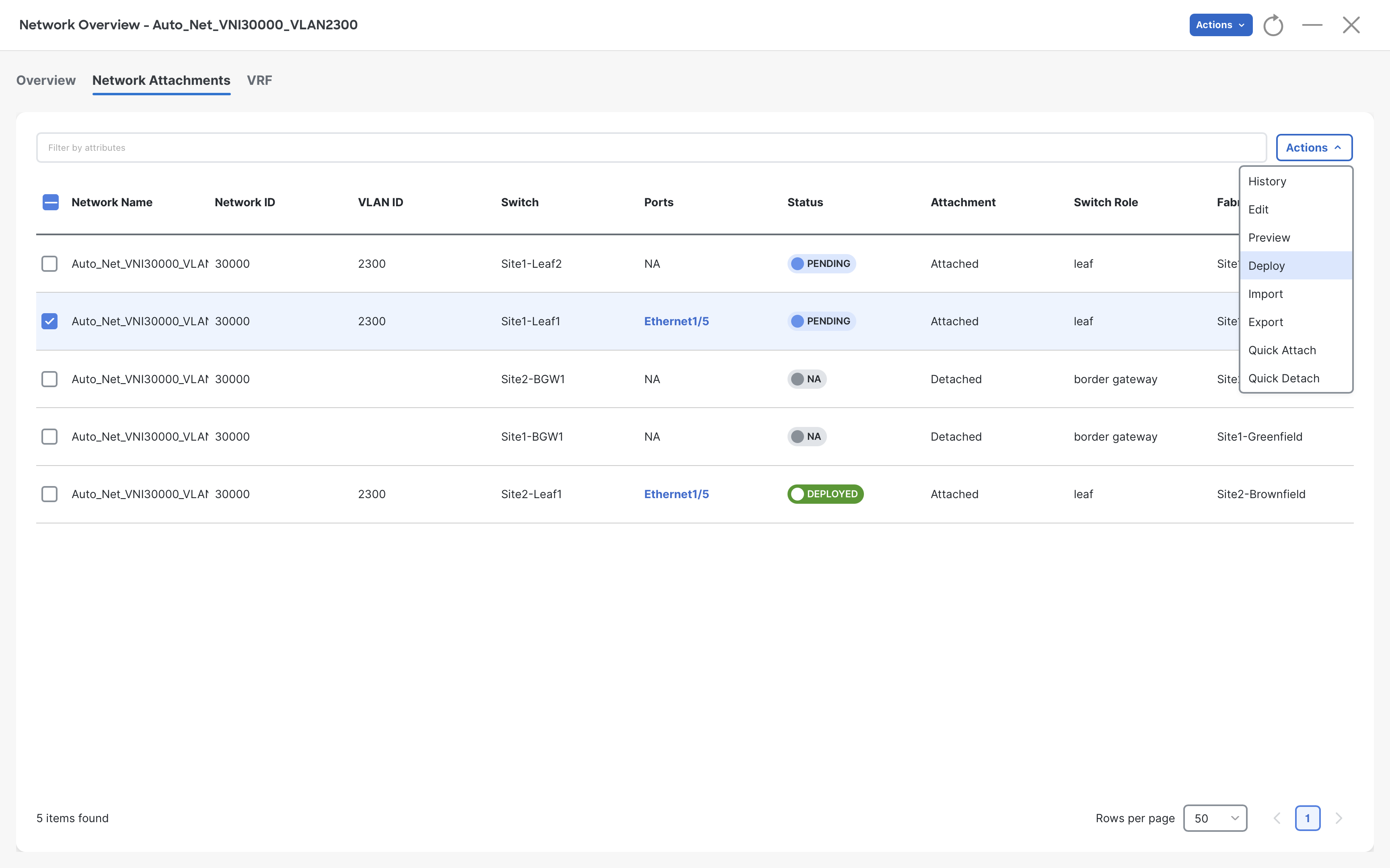
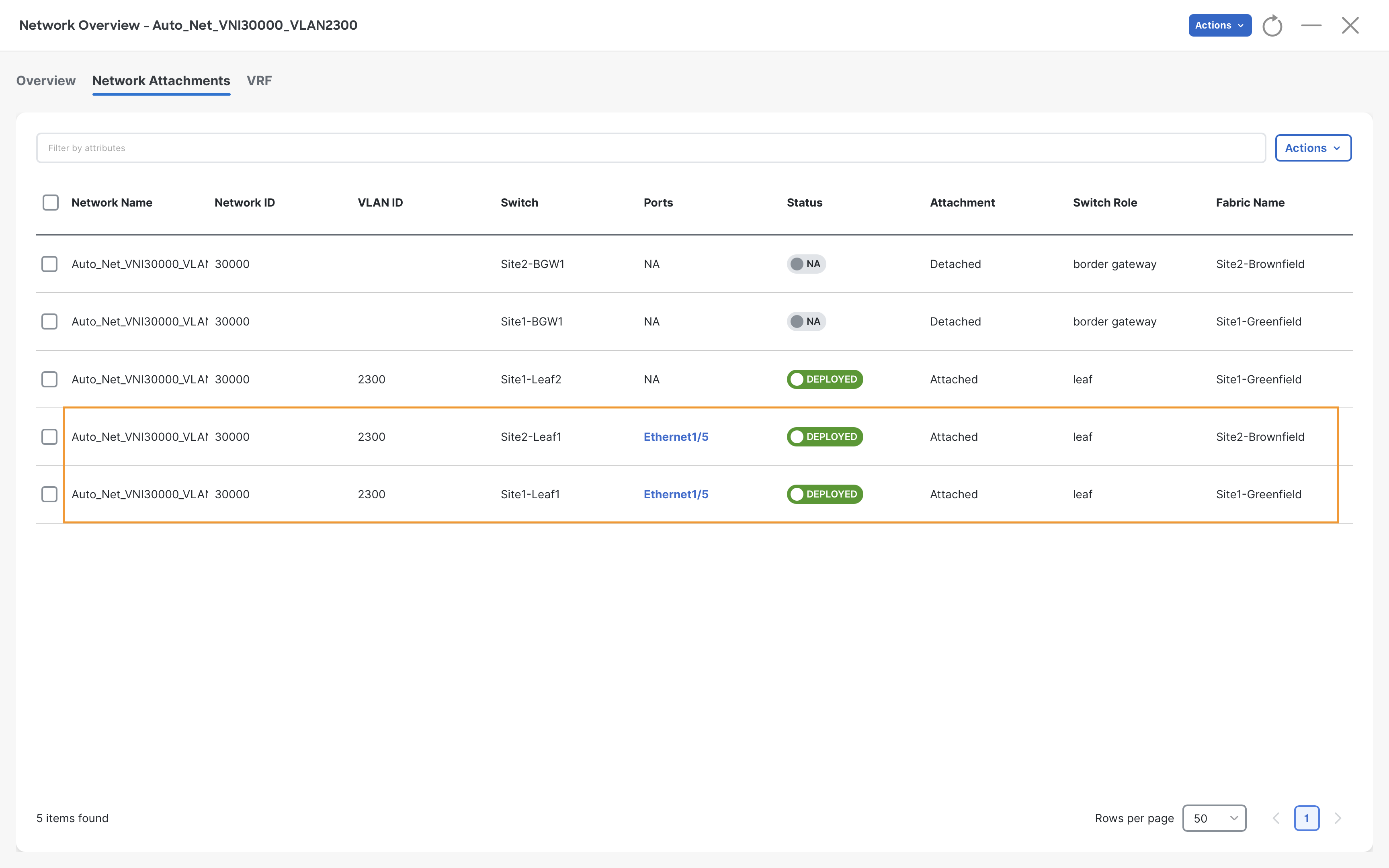
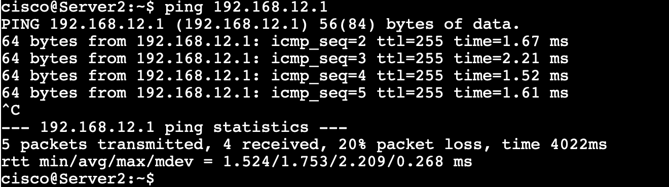
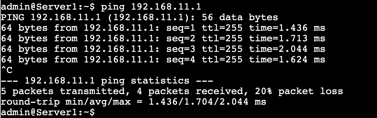
A successful ping test to the Gateway IP 192.168.11.1 from Server1 confirms this network has been attached correctly.
Server1
ping 192.168.11.1
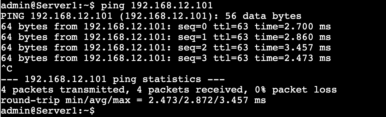
Also, we can ping Server2 from Server1
Server1
ping 192.168.12.101
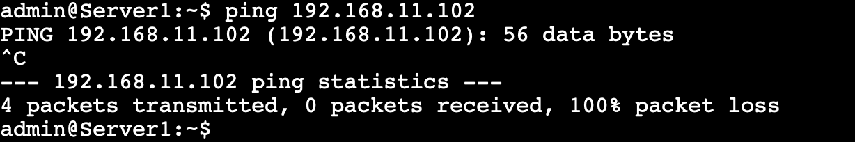
But we cannot ping Server3 located in Site2-Brownfield because this VRF has not been extended between the two VXLAN sites
Server1
ping 192.168.11.102
The same can also be verified from NDFC. We can see these networks are not attached to Site1-BGW1 & Site2-BGW1 and therefore are not extended over the VXLAN Multisite.
Stretching Networks/VRFs across the Sites
Note
We are extending the networks which will allow us to stretch the broadcast domain for both segments. NDFC also allows us to stretch only the VRF, but that would make sense only if none of the networks were stretched.
To extend the networks over the VXLAN Multisite, we need to attach them to the Border Gateways (BGWs) of both the sites using the following steps:
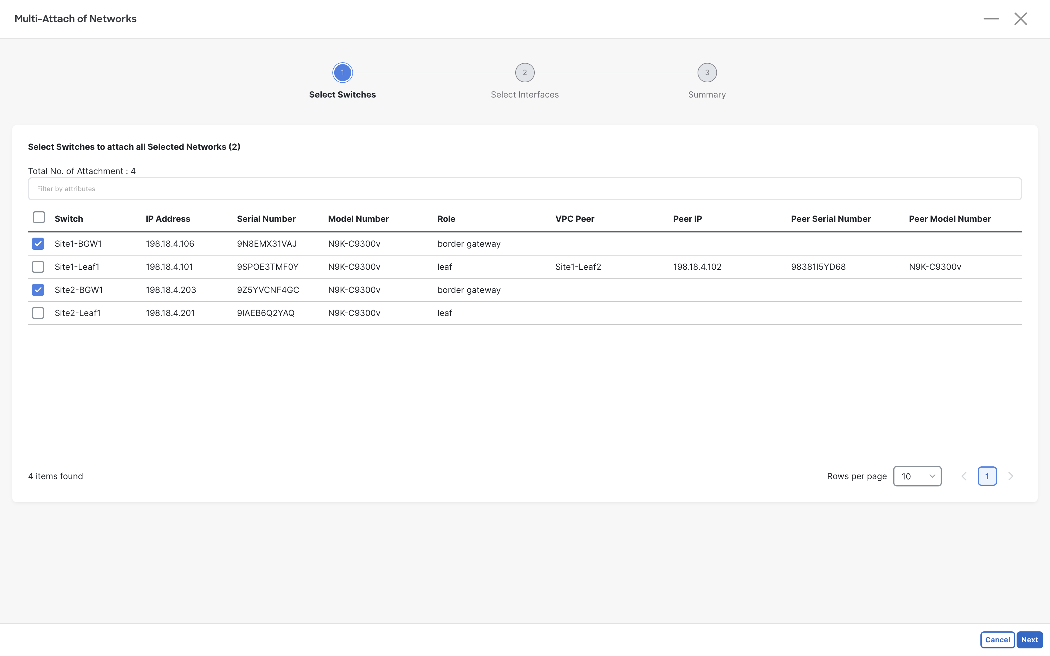
Step 1- Select both networks and click Multi-Attach from Actions
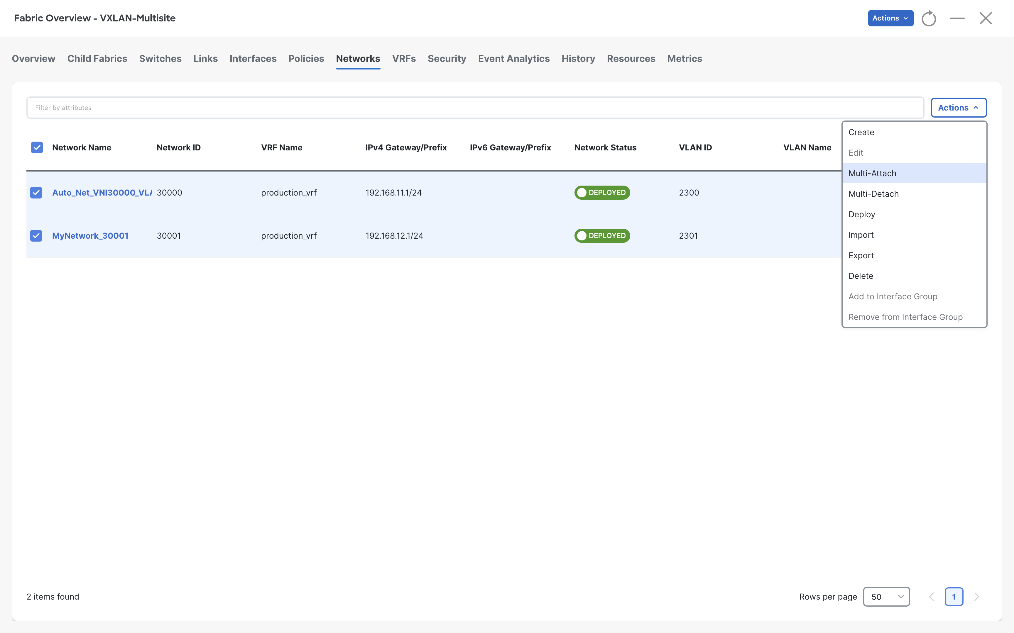
Step 2- Select both BGWs and click Next
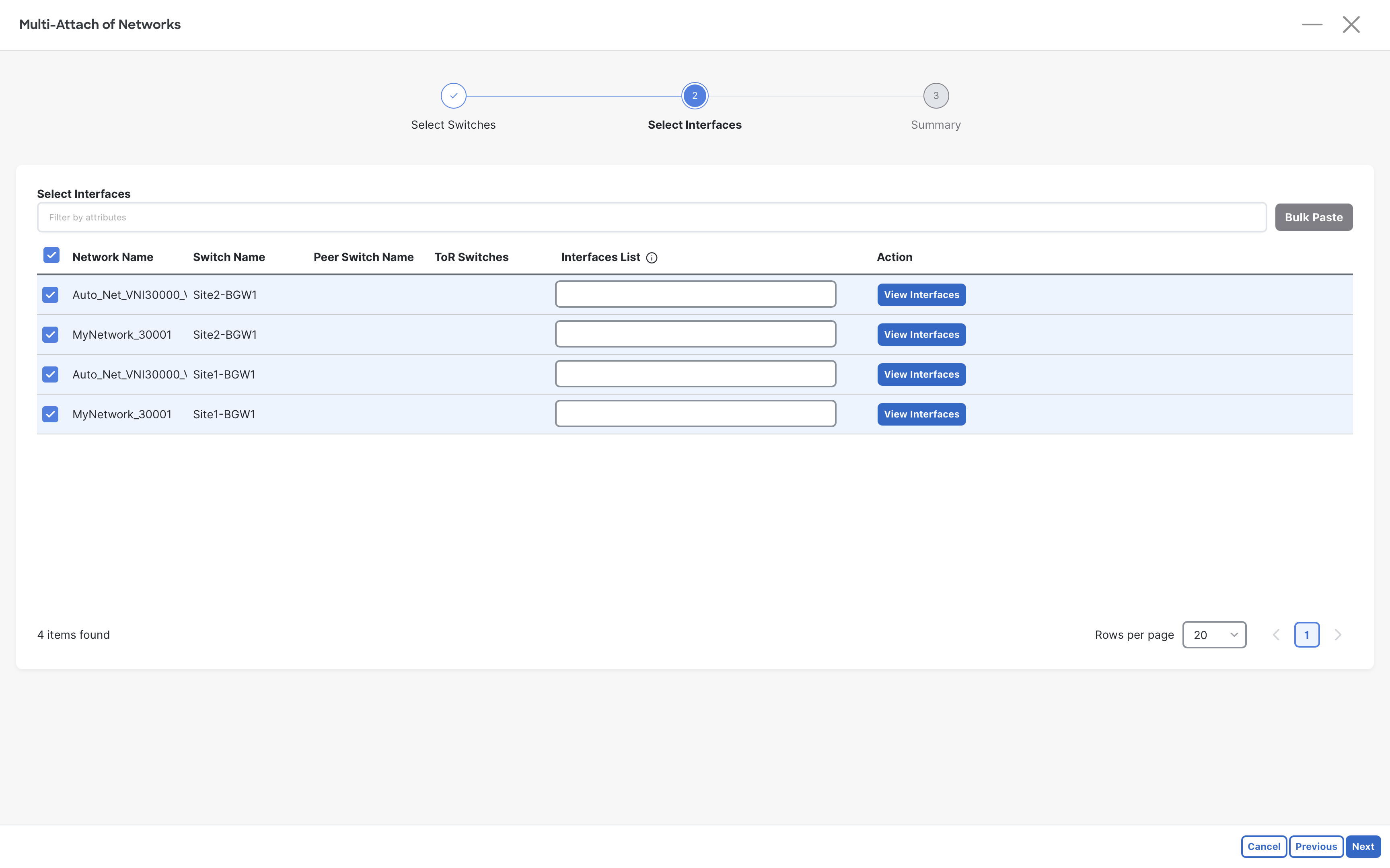
Step 3- Click Next without selecting any interfaces of BGWs. As long as the VLAN is configured there things will work.
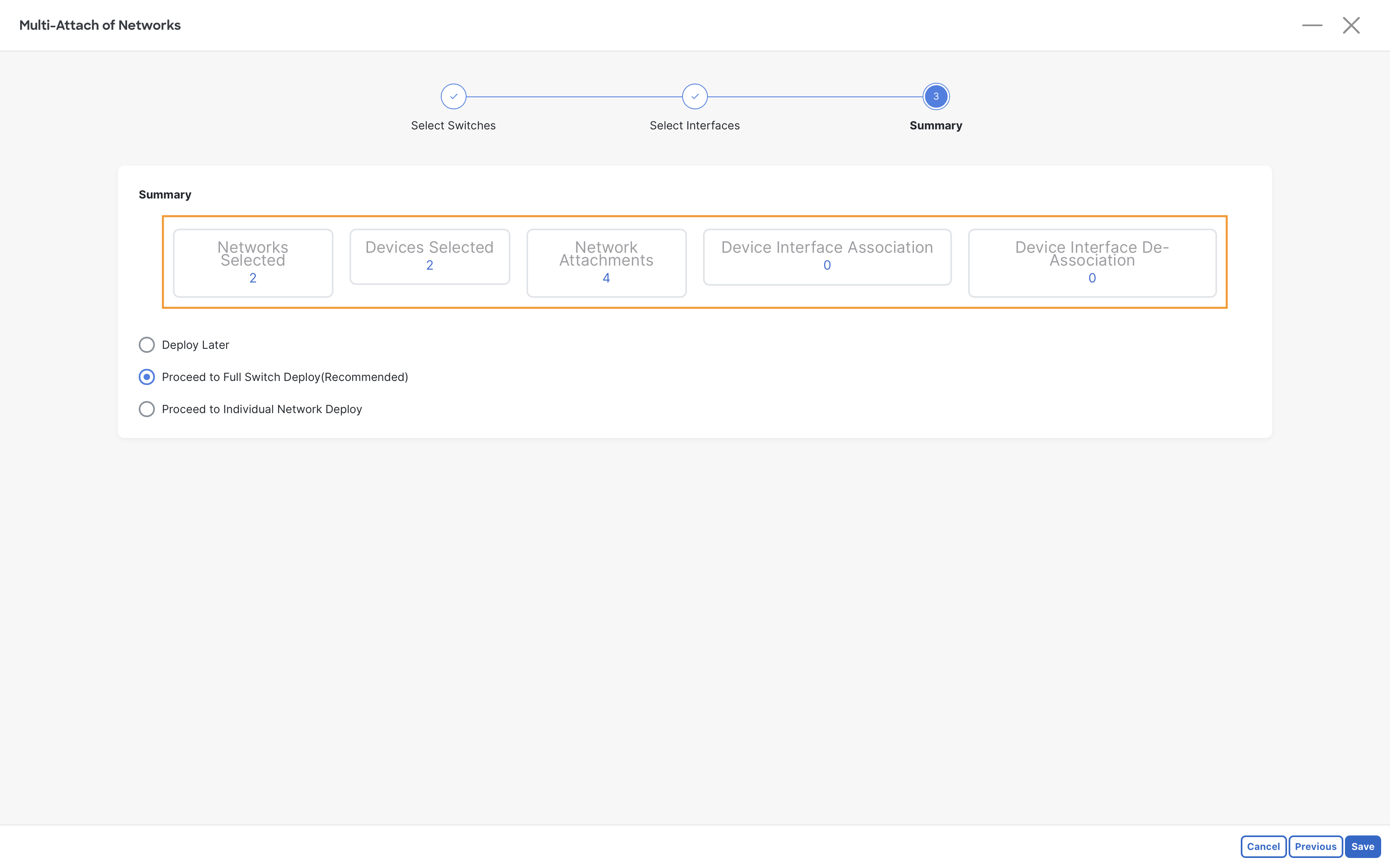
Step 4- Click Save to proceed with full switch deployment
Step 5- Click Deploy All to deploy the config to the switches.
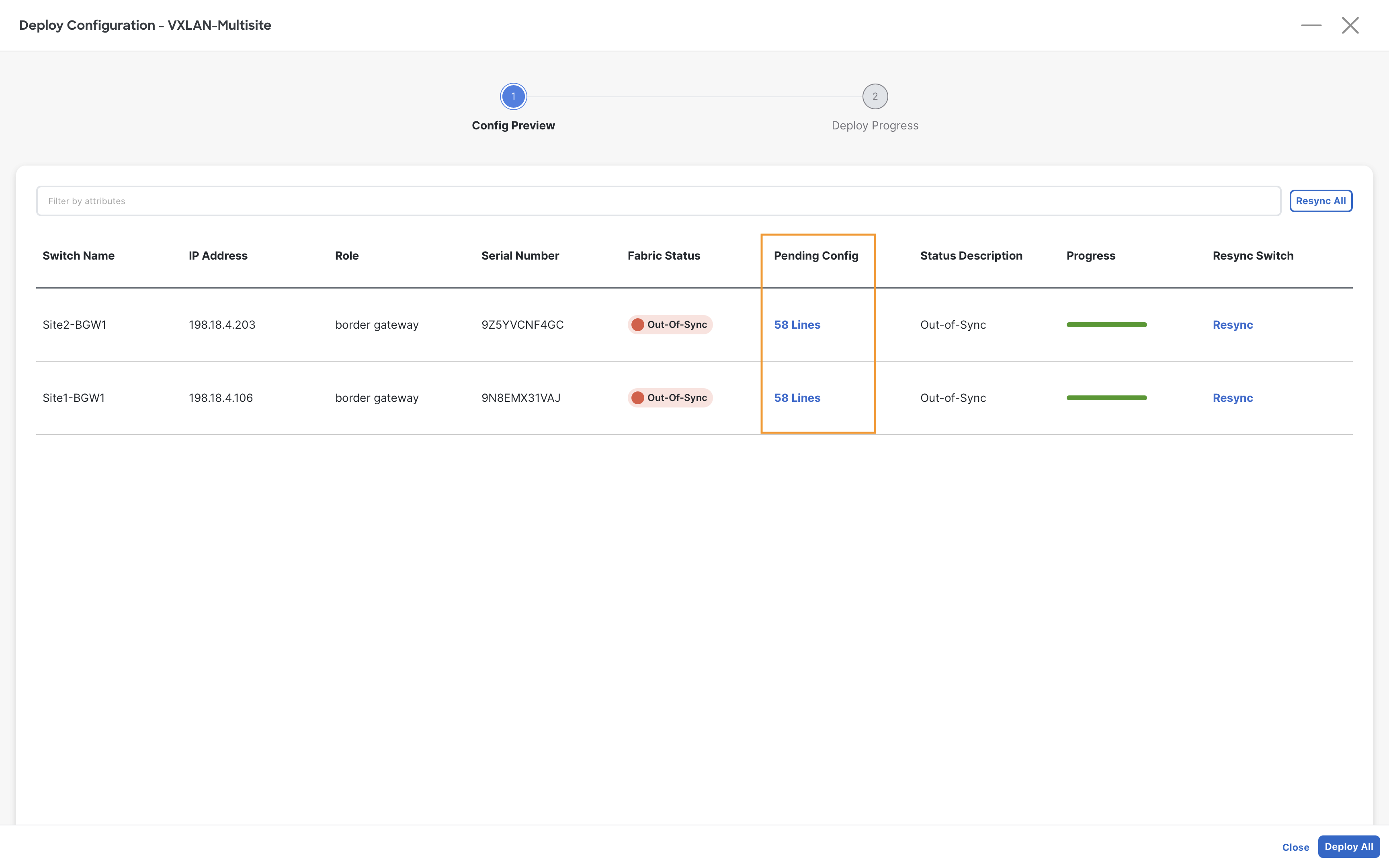
Step 6 - Once the deployment completes, click Close
Verification
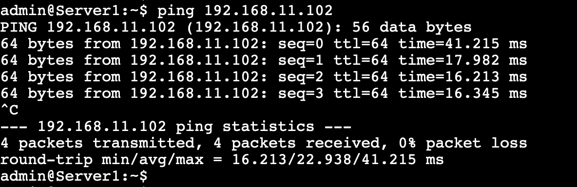
Conduct a ping test from Server1 at Site1-Greenfield to Server3 at Site2-Brownfield
Server1
ping 192.168.11.102
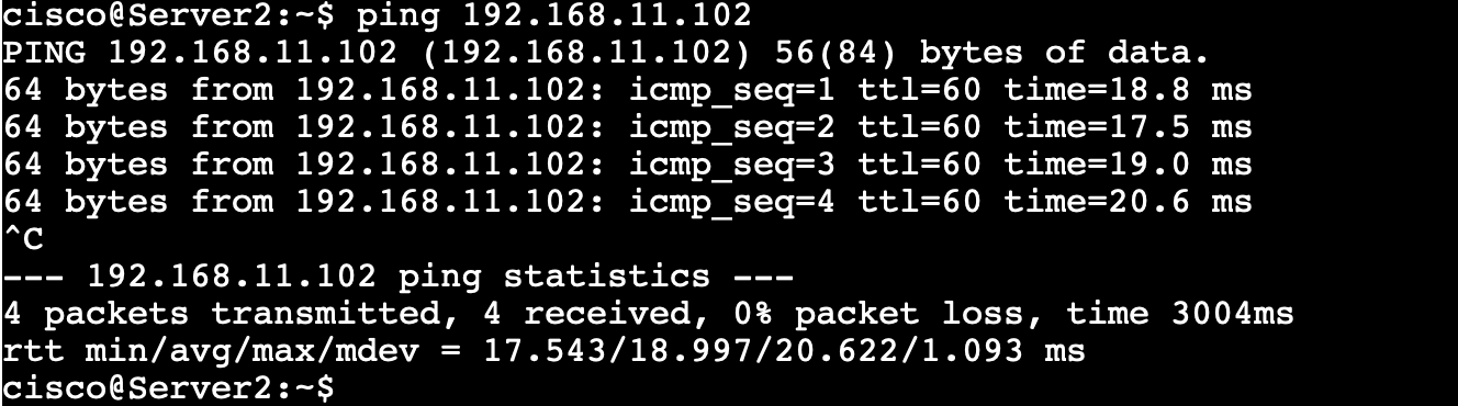
Conduct a ping test from Server2 at Site1-Greenfield to Server3 at Site2-Brownfield
Server2
ping 192.168.11.102
You can continue now with Task #4